Choose an answer for each question. (You will choose three answers in total.) Question_1: Determine the collector current le of Q, for the circuit shown below. 4Alttali dourei Question_2: Determine the base-emitter voltage VBg of Q, for the circuit shown below. istärünün baz Question_3: Calculate the maximum value of Re that places Q, at the edge of the active region. el hälo Circuit Parameters /| Vcc=8V, Is = 5x10-16 A. B = 110, VA=00 Rc -Vc 10 μΑ(
Choose an answer for each question. (You will choose three answers in total.) Question_1: Determine the collector current le of Q, for the circuit shown below. 4Alttali dourei Question_2: Determine the base-emitter voltage VBg of Q, for the circuit shown below. istärünün baz Question_3: Calculate the maximum value of Re that places Q, at the edge of the active region. el hälo Circuit Parameters /| Vcc=8V, Is = 5x10-16 A. B = 110, VA=00 Rc -Vc 10 μΑ(

Introductory Circuit Analysis (13th Edition)
13th Edition
ISBN:9780133923605
Author:Robert L. Boylestad
Publisher:Robert L. Boylestad
Chapter1: Introduction
Section: Chapter Questions
Problem 1P: Visit your local library (at school or home) and describe the extent to which it provides literature...

Related questions
Question
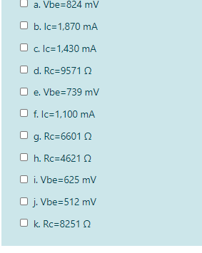
Transcribed Image Text:a. Vbe=824 mV
b. Ic=1,870 mA
O c. Ic=1,430 mA
O d. Rc=9571 n
e. Vbe=739 mV
O f. Ic=1,100 mA
O g. Rc=6601 Q
O h. Rc=4621 Q
O i. Vbe=625 mV
O j. Vbe=512 mv
O k. Rc=8251 Q
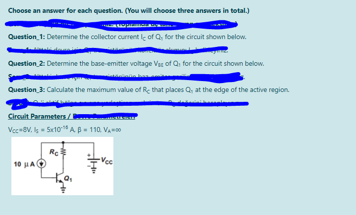
Transcribed Image Text:Choose an answer for each question. (You will choose three answers in total.)
Question_1: Determine the collector current Ic of Q, for the circuit shown below.
Atali deuraic
Question_2: Determine the base-emitter voltage VBg of Q; for the circuit shown below.
istärünün bar
Question_3: Calculate the maximum value of Rc that places Q; at the edge of the active region.
Circuit Parameters /
Vcc=8V, Is = 5x10-18 A. B = 110, VA=0
Rc
-Vcc
10 μΑ
Expert Solution
This question has been solved!
Explore an expertly crafted, step-by-step solution for a thorough understanding of key concepts.

Step by step
Solved in 3 steps with 2 images

Knowledge Booster


Learn more about
Need a deep-dive on the concept behind this application? Look no further. Learn more about this topic, electrical-engineering and related others by exploring similar questions and additional content below.Recommended textbooks for you
Introductory Circuit Analysis (13th Edition)
Electrical Engineering
ISBN:
9780133923605
Author:
Robert L. Boylestad
Publisher:
PEARSON

Delmar's Standard Textbook Of Electricity
Electrical Engineering
ISBN:
9781337900348
Author:
Stephen L. Herman
Publisher:
Cengage Learning

Programmable Logic Controllers
Electrical Engineering
ISBN:
9780073373843
Author:
Frank D. Petruzella
Publisher:
McGraw-Hill Education
Introductory Circuit Analysis (13th Edition)
Electrical Engineering
ISBN:
9780133923605
Author:
Robert L. Boylestad
Publisher:
PEARSON
Delmar's Standard Textbook Of Electricity
Electrical Engineering
ISBN:
9781337900348
Author:
Stephen L. Herman
Publisher:
Cengage Learning
Programmable Logic Controllers
Electrical Engineering
ISBN:
9780073373843
Author:
Frank D. Petruzella
Publisher:
McGraw-Hill Education

Fundamentals of Electric Circuits
Electrical Engineering
ISBN:
9780078028229
Author:
Charles K Alexander, Matthew Sadiku
Publisher:
McGraw-Hill Education

Electric Circuits. (11th Edition)
Electrical Engineering
ISBN:
9780134746968
Author:
James W. Nilsson, Susan Riedel
Publisher:
PEARSON

Engineering Electromagnetics
Electrical Engineering
ISBN:
9780078028151
Author:
Hayt, William H. (william Hart), Jr, BUCK, John A.
Publisher:
Mcgraw-hill Education,