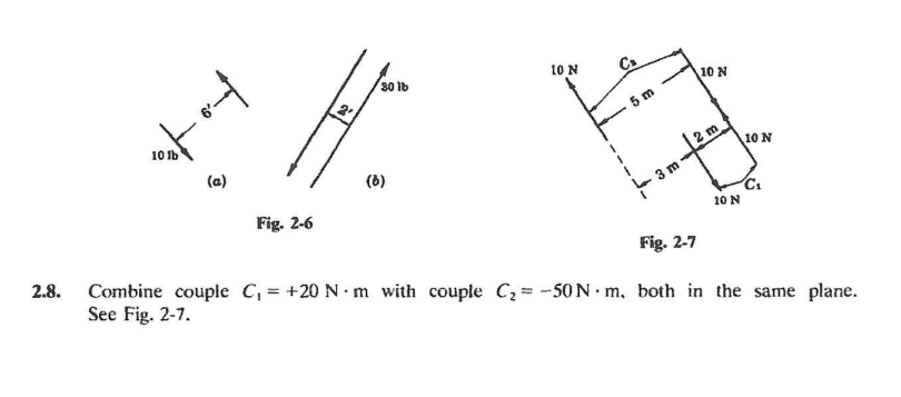
Combine couple C, = +20 N - m with couple Cz= -50N· m, both in the same plane.


Q: Replace the two forces and single couple by an equivalent force-couple system at point A. Ans. R =…
A:
Q: If vectors 8i – 7j + 11Xk and - 2i – 9Xj+ 7Xk are perpendicular, solve for one possible value of X.…
A: The first vector is, a→=8i-7j+11Xk The second vector is, b→=-2i-9Xj+7Xk
Q: 650 N 500 N 30 300 N 1500 N - m 60° B -5 m- -2 m- Replace the loading system acting on the post by…
A:
Q: For the drawing shown, find the moment at * (- point (A) (Clock + and counter clock 1m F=7 kN 4m A…
A:
Q: What is the magnitude of the reaction couple at point A in kN-m? 20° D A B 0.8 m - 1.8 m 0.4 m 25 kN
A: The free-body diagram of the structure is given below,
Q: =M- 400x 0.15cos30-320x0.30 %3D 160 400 N mm = 148 Nm CCW cample : Replace the three forces acting…
A:
Q: 3) Solve vectorially the rotation effect that F force will create on the hinge axis. F=886 05 m' B.…
A:
Q: Solve For the sum oF moment of all Forces dockwise direction is pasitive at point A, B,r GD. Include…
A:
Q: 2m SAMPLE PROBLEM 2/5 40 Calculate the magnitude of the moment about the base point O of the 600-N…
A: Given, F = 600 N
Q: The shear and bending-moment diagrams V (kN) - 4- 9- M(KN.m) 6 2 4- O True False
A: The shear force diagram is not represent values of different parameter with moment diagram…
Q: Calculate the moment at point C of the three forces shown in figure (clockwise + and counter…
A: The schematic diagram of the system is as follows:
Q: he moment of Load-B about Point-A has a magnitude of _____ N*m
A: moment = force x perpendicular distance of support from line of action
Q: 37 N-m The braket shown in figure is subjected to three forces and one couple as Shown in figure.…
A: Calculate the net forces in the x-direction, Fx=600 N×cos30°-120 N=399.615 N Calculate the net force…
Q: 1 A 150-N pull T is applied to a cord, which is wound securely around the inner hub of the drum.…
A: As per given Force =150 N r1=0.125m r2=0.2m We have determine moment T and angle
Q: Calculate the moment at point (A) of the forces shown in figure. T=10 2.5 m-1 T-3N 2.5 m T T3=6 N…
A:
Q: Question 1: If e=30°, replace the three couples shown in figure (1) below into a) one couple system…
A:
Q: 4. Replace the system of forces and couples shown in Fig. 3.40 by a single force and couple at point…
A: To replace the system of forces and couples by a single force and couple at point a.
Q: Q10/ The value of shear force (VB) at * :the roller B is Point D 10 kN Point E h-200 mm 50 mm 2 kN…
A:
Q: 8 kN 2) Find the torque created by the 2 forces about the origin. Ignore the 15 kNm load. (It is…
A:
Q: Replace force F = -2800i + 1600j + 4000k N acting at end A of the crank handle with a force R acting…
A: Given data F = -2800i + 1600j + 4000k N
Q: By mean S of th replace the Force system shown in Figure by a force along line AB and a couple ?. 3N…
A: For the given system shown consider the force system as shown below, There will be two couple by 3…
Q: Compute the moment of these forces as shown in the figure with respect to point A. 6 kN 30 30 1.5 m…
A:
Q: Question 1 8 kN/m 5 kN/m A 1200 N-m couple moment is applied at B in the direction shown. Find the…
A:
Q: 2/48 Calculate the moment MA of the 200-N force about point A by using three scalar methods and one…
A:
Q: 12:Replace the Force 70N by Equivalent System consist of one force &couple at 1: At Supporting point…
A:
Q: Q2/compute the moment of force 650 N about the rod AB. 125 mm 150 mm 150 mm 100 m 300man-
A:
Q: 1. Calculate the moment at point (A) of the forces shown in figure. T:=10 2.5 m _ 2.5 im _ | T;=3 N…
A: Solution:
Q: 1. Calculate the moment at point (A) of the forces shown in figure. T;-10 2.5 m-25m-I T;-3 N T3=6 N…
A:
Q: Q3/ Shown in fig.( 3 ) replace the loading system by an equivalent resultant force and couple moment…
A: Although if we calculate the reaction at point A we will get different answer but here is asked…
Q: 40 N 0.3 m A 0.1 m 0.3 m 40 N (a)
A:
Q: L7 Calculate the moment at point C of the three forces shown in figure (clockwise *(- + and counter…
A: The free body diagram of the force system is as follows:
Q: Determine the maximum moment in kN m in the figure below. 16 kN | 4 kN/m 20 kN 2 kN/m A |D - 4 m →-…
A:
Q: The figures show a frame and its FBDS. If an additional couple moment is applied at A, then how will…
A: Solution:
Q: Example 6: Replace the force and couple system acting on the member shown by an equivalent resultant…
A:
Q: The magnitude of the moment of the force F=300i-200j+600k N about the y-axis is.  Select one: a.…
A:
Q: 40 N 0.3 m A B- 0.1 m 0.3 m 40 N (a)
A:
Q: The magnitude of fixed end moment developed at support A is. kNm. 12 kN/m A B 12 m-
A:
Q: Q6: For the force-Couple system shown in figure (6); determine an eguivalent couple (M) and…
A:
Q: 1 ft 3 ft 3 ft B (-9001 + 8003 + 1000k) Ib.ft 3 ft D 6 ft 3 ft E (-3008 – 400 + 10ok) Ibs The…
A:
Q: Solve For the sum of moment of all Forces dlockwise direction is pasitive at point A, B, C AND D 2m…
A: GIVEN DATA A SYSTEM OF FORCE IS GIVEN WE HAVE TO FIND MOMENT ABOUT POINT A, B ,C & D
Q: Q2. The gear is subjected to the two forces shown in Figure (Q2). Replace these forces by an…
A:
Q: (a1) Replace the system shown below by a single force at B and a couple. 700 N 450 N 300 N |30 60 B…
A: It can be observed that at A the support is fixed, this implies that there will be two reactions,…
Q: Practice Problem 2.4.14: Which of the systems are 10 N equivalent to the couple to the figure at the…
A:
Q: Calculate the total moment of the system shown in Figure about point O, when P1 = 3 kN, P2 = 3 kN…
A:
Q: y 400 тm В to 250 тm 20° A А
A:
Q: 8 kN/m 5 kN/m to 1.5 m -0.75 m 0.75 m What is the moment induced by this distributed load at O…
A:
Q: 400 N Calculate the moment k-100 mm 60° of the 400-N force about point o in five differ- ent ways.…
A:
Q: Q3: Replace the force and couple system shown in figure by an equivalent force and couple moment…
A: The free body diagram o the beam is as follows:
Q: What is the Maximum moment in kN-m. Given: w1 = 45, w2 = 18, a 2, b = 4, and c-2. %3! IO w1 kN/m w2…
A: To determine the maximum bending moment.
Q: -3 m- 30° W 2 m 31000 N 4 m 5 m
A: As multiple questions are asked in a single request, the solution is provided to only first…
Subject: Static of rigid bodies

Step by step
Solved in 2 steps

- Space Frame ABC is clamped at A, except it is free to rotate at A about the x and y axes. Cables DC and EC support the frame at C. Force Py= - 50 lb is applied at the mid-span of AS, and a concentrated moment Mx= -20 in-lb acts at joint B. (a) Find reactions at support A. (b) Find cable tension Forces.A 5 m beam is fixed at one end and pinned at other end. It is loaded a couple M at pinned end. If there is one unit rotation at the pinned connected end, EI = 1800 N.m^21. Which of the following gives the value of couple M in N.m at the pinned end? a. 1444b. 4414c. 4441d. 14142. Which of the following gives the value of vertical reaction at pinned end in N? a. 334b. 434c. 443d. 3443. Which of the following gives the value of moment at fixed end in N.m.? a. 334b. 434c. 443d. 344The system is made up of a bar, supported by a pin at point A and by a smooth collar at point B (the collar slides on the ABG bar). The collar is pinned to bar BDE, and bar BDE is supported by a pin at D and a cable at end E. Draw the bar BDR horizontaly and generate the cutting force diagram, flexing moment,show the max values of cutting force and flexing moment and its position . With T=26lb, a=4 in, b=9 in
- (a) Replace force F = -2800i + 1600j + 4000k N acting at end A of the crank handle with a force R acting at O and a couple-vector C. (b) Resolve R into the normal component P (normal to the cross-section of the shaft) and the shear component V (in the plane of the cross-section) (c) Resolve C into the twisting component T and the bending moment M. Please answer CIn the figure below, all the bearings are movable bearings and the C bearing is in an inclined position. Draw the M, N, T diagrams according to your force values. (20kN force is perpendicular to the beam it acts on. P1, P2, P3 forces are in the vertical direction.) q=7 kN/m P1=25 kN P2=27 kN P3=11 kNRod AB is fixed to a smooth collar D, which slides freely along the vertical guide shown below. Point C is located just to the left of the concentrated load P = 40 lb. Suppose that w = 11 lb/ft. Follow the sign convention. a) Determine the normal force at point C. Express your answer in pounds to three significant figures. b) Determine the shear force at point C. Express your answer in pounds to three significant figures. c) Determine the moment at point C. Express your answer in pound-feet to three significant figures.
- F, a triangular distributed load and couple moments M1,...,M6 are applied a rigid frame structure which has a fixed support at A. Distributed load is in the negative z direction and couple moments are parallel to one of the x, y or z axis. All members of the frame structure are rigidly connected and parallel to one of the x, y or z axis. Find the support reactions. (Neglect the dimensions of the frame members)3- F1, +y in the –z direction to the bent AEB pipe in the figure. F2 forces are applied in the direction of One from end of pipe A supported by a ball joint; also BD and BC balanced with cables. Accordingly, the BD cable Calculate the strength of the force. F1=(9)kN, F2 =10kN, h = (6)mFind the internal force system acting on section 3 for the pin-connected frame. a P = 255 N (C), V = 0, M = 29.8 N · m b P = 255 N (T), V = 0, M = 29.8 N · m c P = 255 N (C), V = 0, M = 92.8 N · m d P = 525 N (C), V = 0, M = 29.8 N · m
- l4//me shear and bending moment diagram as shown in figure. by graphical method. 132.5KN 122.5KN.m ) sgN/m b itwd L oe—dine—dThe shaft, is driven by pulley B from an electric motor. Another belt drivefrom pulley A is running a compressor. The belt tensions for pulley A are 1500 N and 600 N. The ratioof belt tensions for pulley B is 3.5. The diameter of pulley A is 150 mm and the diameter of pulley B is 480 mm. The allowable tensilestress for the shaft material is 170 MPa and the allowable shear stress is 85 MPa. Taking torsion andbending factors as 1.25 and 1.75 respectively, find the shaft diameter.Also find out the dimensions for a hollow shaft with outside diameter limited to 30 mm. Compare theweights of the two shafts. [Ans. 30 mm ; 24 mm ; 1.82 Given Length CD=350mm Length AB=150mm Length BD=100mm The total length is CD =350Cite 5 example on the applications of moment couple in our everyday life and describehow is moment couple applied in each example.