Compute for the following and draw the power triangle a. Real power b. Reactive power c. Apparent power II 10nF 1₂ E (~ IKR 474F TOOMM 4.1k0 F2 E = 25 sin(350t +20) Is -C₂ F3
Compute for the following and draw the power triangle a. Real power b. Reactive power c. Apparent power II 10nF 1₂ E (~ IKR 474F TOOMM 4.1k0 F2 E = 25 sin(350t +20) Is -C₂ F3

Power System Analysis and Design (MindTap Course List)
6th Edition
ISBN:9781305632134
Author:J. Duncan Glover, Thomas Overbye, Mulukutla S. Sarma
Publisher:J. Duncan Glover, Thomas Overbye, Mulukutla S. Sarma
Chapter2: Fundamentals
Section: Chapter Questions
Problem 2.22P: The real power delivered by a source to two impedances, Z1=4+j5 and Z2=10 connected in parallel, is...

Related questions
Question
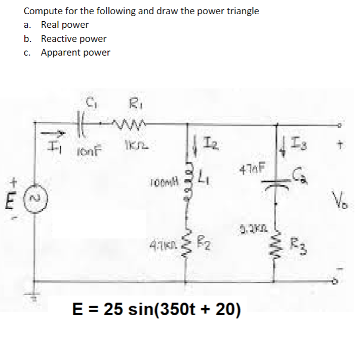
Transcribed Image Text:Compute for the following and draw the power triangle
a. Real power
b. Reactive power
c. Apparent power
II 10nF
1₂
E (~
IKR
474F
TOOMM
4.1k0
F2
E = 25 sin(350t +20)
Is
-C₂
F3
Expert Solution
This question has been solved!
Explore an expertly crafted, step-by-step solution for a thorough understanding of key concepts.

Step by step
Solved in 4 steps with 4 images

Knowledge Booster


Learn more about
Need a deep-dive on the concept behind this application? Look no further. Learn more about this topic, electrical-engineering and related others by exploring similar questions and additional content below.Recommended textbooks for you
Power System Analysis and Design (MindTap Course …
Electrical Engineering
ISBN:
9781305632134
Author:
J. Duncan Glover, Thomas Overbye, Mulukutla S. Sarma
Publisher:
Cengage Learning
Power System Analysis and Design (MindTap Course …
Electrical Engineering
ISBN:
9781305632134
Author:
J. Duncan Glover, Thomas Overbye, Mulukutla S. Sarma
Publisher:
Cengage Learning