Consider a coaxial cable, filled with a non-magnetic dielectric with relative dielectric constant & = 1.9. The cable has a characteristic impedance Z, = 75 Q and is 60 cm long. It is terminated to the right by a resistor R1 = 35 N in series with an inductor L, = 10 nH, and connected on the left to a generator with internal resistance Rg = 75 N. The generator produces a steady-state sinusoidal signal of amplitude VG = 1 V at frequency f = 800 MHz. The circuit is depicted in Figure 5 below. RG = 75N 60 cm R = 35 N VG Z0 = 75 N L, = 10 nH Figure 5 (i) The diameter of the inner conductor of the coaxial cable is d. = 1 mm. Calculate the diameter D. of the outer conductor. (ii) Using the Smith chart, calculate the reflection coefficient r, at the load. (iii) along the line to measure the value of the voltages along it. What is the minimum voltage you expect to measure? Suppose you can insert a slotted line between the cable and the load, and scan
Consider a coaxial cable, filled with a non-magnetic dielectric with relative dielectric constant & = 1.9. The cable has a characteristic impedance Z, = 75 Q and is 60 cm long. It is terminated to the right by a resistor R1 = 35 N in series with an inductor L, = 10 nH, and connected on the left to a generator with internal resistance Rg = 75 N. The generator produces a steady-state sinusoidal signal of amplitude VG = 1 V at frequency f = 800 MHz. The circuit is depicted in Figure 5 below. RG = 75N 60 cm R = 35 N VG Z0 = 75 N L, = 10 nH Figure 5 (i) The diameter of the inner conductor of the coaxial cable is d. = 1 mm. Calculate the diameter D. of the outer conductor. (ii) Using the Smith chart, calculate the reflection coefficient r, at the load. (iii) along the line to measure the value of the voltages along it. What is the minimum voltage you expect to measure? Suppose you can insert a slotted line between the cable and the load, and scan

Introductory Circuit Analysis (13th Edition)
13th Edition
ISBN:9780133923605
Author:Robert L. Boylestad
Publisher:Robert L. Boylestad
Chapter1: Introduction
Section: Chapter Questions
Problem 1P: Visit your local library (at school or home) and describe the extent to which it provides literature...

Related questions
Question
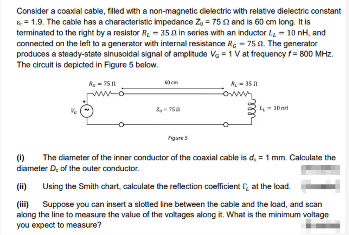
Transcribed Image Text:Consider a coaxial cable, filled with a non-magnetic dielectric with relative dielectric constant
&, = 1.9. The cable has a characteristic impedance Z, = 75 Q and is 60 cm long. It is
terminated to the right by a resistor R1 = 35 N in series with an inductor L, = 10 nH, and
connected on the left to a generator with internal resistance Rç = 75 N. The generator
produces a steady-state sinusoidal signal of amplitude VG = 1 V at frequency f = 800 MHz.
The circuit is depicted in Figure 5 below.
RG = 75 1
60 cm
RL = 35 N
wwo
Za = 75 N
L = 10 nH
Figure 5
(i)
The diameter of the inner conductor of the coaxial cable is d. = 1 mm. Calculate the
diameter D. of the outer conductor.
(ii)
Using the Smith chart, calculate the reflection coefficient r, at the load.
(iii) Suppose you can insert a slotted line between the cable and the load, and scan
along the line to measure the value of the voltages along it. What is the minimum voltage
you expect to measure?
Expert Solution
This question has been solved!
Explore an expertly crafted, step-by-step solution for a thorough understanding of key concepts.

Step by step
Solved in 4 steps with 1 images

Knowledge Booster


Learn more about
Need a deep-dive on the concept behind this application? Look no further. Learn more about this topic, electrical-engineering and related others by exploring similar questions and additional content below.Recommended textbooks for you
Introductory Circuit Analysis (13th Edition)
Electrical Engineering
ISBN:
9780133923605
Author:
Robert L. Boylestad
Publisher:
PEARSON

Delmar's Standard Textbook Of Electricity
Electrical Engineering
ISBN:
9781337900348
Author:
Stephen L. Herman
Publisher:
Cengage Learning

Programmable Logic Controllers
Electrical Engineering
ISBN:
9780073373843
Author:
Frank D. Petruzella
Publisher:
McGraw-Hill Education
Introductory Circuit Analysis (13th Edition)
Electrical Engineering
ISBN:
9780133923605
Author:
Robert L. Boylestad
Publisher:
PEARSON
Delmar's Standard Textbook Of Electricity
Electrical Engineering
ISBN:
9781337900348
Author:
Stephen L. Herman
Publisher:
Cengage Learning
Programmable Logic Controllers
Electrical Engineering
ISBN:
9780073373843
Author:
Frank D. Petruzella
Publisher:
McGraw-Hill Education

Fundamentals of Electric Circuits
Electrical Engineering
ISBN:
9780078028229
Author:
Charles K Alexander, Matthew Sadiku
Publisher:
McGraw-Hill Education

Electric Circuits. (11th Edition)
Electrical Engineering
ISBN:
9780134746968
Author:
James W. Nilsson, Susan Riedel
Publisher:
PEARSON

Engineering Electromagnetics
Electrical Engineering
ISBN:
9780078028151
Author:
Hayt, William H. (william Hart), Jr, BUCK, John A.
Publisher:
Mcgraw-hill Education,