Consider the circuit diagram below. Draw the power triangle for this circuit and compute the power factor. Note that the magnitude of vi(t) is given in peak volts (not RMS). R1 150 0 ww v, (t) 5 V L1 120 µF 850 mH 30 Hz
Consider the circuit diagram below. Draw the power triangle for this circuit and compute the power factor. Note that the magnitude of vi(t) is given in peak volts (not RMS). R1 150 0 ww v, (t) 5 V L1 120 µF 850 mH 30 Hz

Power System Analysis and Design (MindTap Course List)
6th Edition
ISBN:9781305632134
Author:J. Duncan Glover, Thomas Overbye, Mulukutla S. Sarma
Publisher:J. Duncan Glover, Thomas Overbye, Mulukutla S. Sarma
Chapter2: Fundamentals
Section: Chapter Questions
Problem 2.1MCQ: The rms value of v(t)=Vmaxcos(t+) is given by a. Vmax b. Vmax/2 c. 2Vmax d. 2Vmax

Related questions
Question
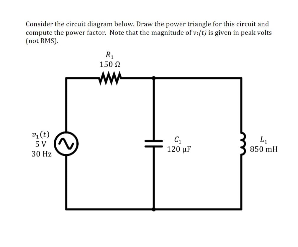
Transcribed Image Text:Consider the circuit diagram below. Draw the power triangle for this circuit and
compute the power factor. Note that the magnitude of vi(t) is given in peak volts
(not RMS).
R1
150 0
ww
v, (t)
5 V
L1
120 µF
850 mH
30 Hz
Expert Solution
This question has been solved!
Explore an expertly crafted, step-by-step solution for a thorough understanding of key concepts.

Step by step
Solved in 3 steps with 1 images

Knowledge Booster


Learn more about
Need a deep-dive on the concept behind this application? Look no further. Learn more about this topic, electrical-engineering and related others by exploring similar questions and additional content below.Recommended textbooks for you
Power System Analysis and Design (MindTap Course …
Electrical Engineering
ISBN:
9781305632134
Author:
J. Duncan Glover, Thomas Overbye, Mulukutla S. Sarma
Publisher:
Cengage Learning
Power System Analysis and Design (MindTap Course …
Electrical Engineering
ISBN:
9781305632134
Author:
J. Duncan Glover, Thomas Overbye, Mulukutla S. Sarma
Publisher:
Cengage Learning