Consider the diode to turn on "hard" at Vp-0.7 for any current i,2 OmA. Sketch the transfer characteristic. Label the voltage where the diode turns on and turns off, and show the limit voltage. 10 2 -1 -2 10 10 9 8 65432 1012 34567 89 10 VI
Consider the diode to turn on "hard" at Vp-0.7 for any current i,2 OmA. Sketch the transfer characteristic. Label the voltage where the diode turns on and turns off, and show the limit voltage. 10 2 -1 -2 10 10 9 8 65432 1012 34567 89 10 VI

Power System Analysis and Design (MindTap Course List)
6th Edition
ISBN:9781305632134
Author:J. Duncan Glover, Thomas Overbye, Mulukutla S. Sarma
Publisher:J. Duncan Glover, Thomas Overbye, Mulukutla S. Sarma
Chapter4: Transmission Line Parameters
Section: Chapter Questions
Problem 4.2P: The temperature dependence of resistance is also quantified by the relation R2=R1[ 1+(T2T1) ] where...

Related questions
Question
clear or dislike
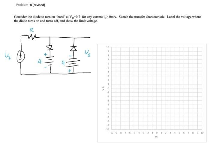
Transcribed Image Text:Problem 8 (revised)
Consider the diode to turn on "hard" at Vp-0.7 for any current ip> OmA. Sketch the transfer characteristic. Label the voltage where
the diode turns on and turns off, and show the limit voltage.
10
9.
4.
3.
-1
-2
-7
-10
10 9 8-7 654 3 210
1 2
89 10
VI
Expert Solution
This question has been solved!
Explore an expertly crafted, step-by-step solution for a thorough understanding of key concepts.

Step by step
Solved in 3 steps with 2 images

Recommended textbooks for you
Power System Analysis and Design (MindTap Course …
Electrical Engineering
ISBN:
9781305632134
Author:
J. Duncan Glover, Thomas Overbye, Mulukutla S. Sarma
Publisher:
Cengage Learning
Power System Analysis and Design (MindTap Course …
Electrical Engineering
ISBN:
9781305632134
Author:
J. Duncan Glover, Thomas Overbye, Mulukutla S. Sarma
Publisher:
Cengage Learning