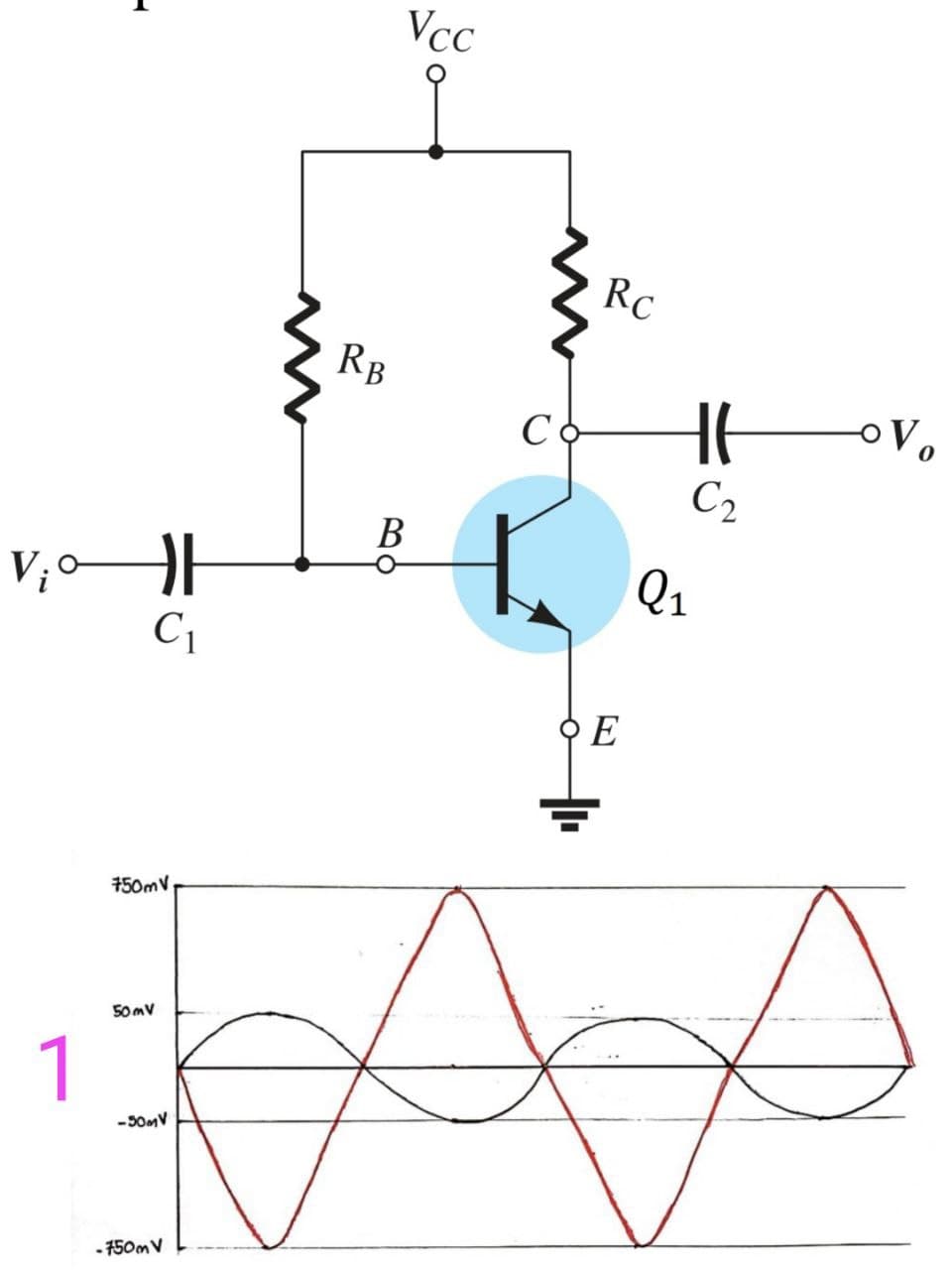
Consider the following common emitter amplifier: Discuss the LIMITATIONS of this circuit in terms of linearity and in terms of impedance matching. I just need the constraints of the circuit, like for example the operating point of the transistor and more. In the images, the graphics are: With the number 1: input-output curve Then a simulation was performed and obtained: With number 2: input-output curve With number 3: more detailed input-output curve With number 4: input-output curve Please I just need the limitations of the circuit based on these graphs.


Power Amplifier
The power amplifier is an electronic amplifier designed to maximize the signal strength of a given input. The input signal strength is enhanced to a high enough level to drive output devices such as speakers, headphones, RF (Radio frequency) transmitters, etc. Unlike voltage / current amplifiers, the power amplifier is designed to drive core loads directly and is used as a storage block in the amplifier series.
Maximum Efficiency Criterion
In every field of engineering, there is a tremendous use of the machine and all those machines are equipped for their popular work efficiency so it very much important for operation engineers to monitor the efficiency of the machine, planning engineers to check out the efficiency of the machine before installing the machine and design engineers to design machine for higher efficiency than and then the utility will procure their products that will ultimately lead to profit and loss of the company. It indicates the importance of efficiency right from the initial stage as manufacturing units, intermediate stage as planning coordinators, and end-users stage as a utility.
Consider the following common emitter amplifier:
Discuss the LIMITATIONS of this circuit in terms of linearity and in terms of impedance matching.
I just need the constraints of the circuit, like for example the operating point of the transistor and more.
In the images, the graphics are:
With the number 1: input-output curve
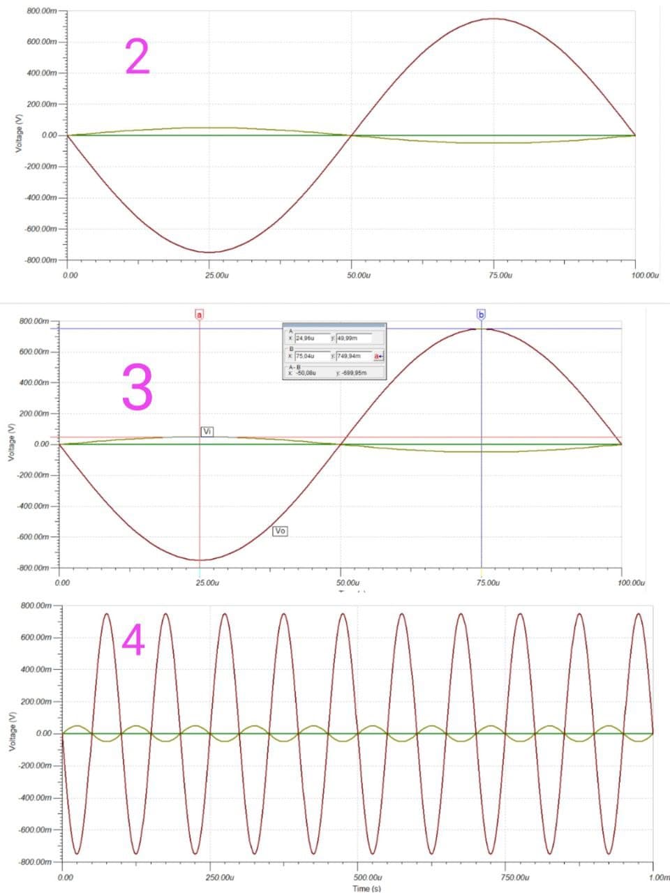
Then a simulation was performed and obtained:
With number 2: input-output curve
With number 3: more detailed input-output curve
With number 4: input-output curve
Please I just need the limitations of the circuit based on these graphs.

Step by step
Solved in 4 steps with 2 images


