Consider the following single half wave AC/AC control with an inductive load. The sup voltage is 29 Volts (rms) and the load resistance is 36 ohms. D1 Th1 2N1599 LI 0 2H Vs 29Vrms SOHZ R1 E360 The figure below shows the output voltage and the load current. Jee e ten Out Vetoge Lond aurent Tine e he The firing angle for Thi is 90 degrees. Assume that the D1 and Thi are lossless. 1. Explain circuit operation, including the shapes of the output voltage and the load current. 2. Derive the equation for the RMS output voitage as a function of firing angle. 3. Sketch the currents through the load (as reference), thyristor and the diode. 4. What are the disadvantages of this circuit arrangement?
Consider the following single half wave AC/AC control with an inductive load. The sup voltage is 29 Volts (rms) and the load resistance is 36 ohms. D1 Th1 2N1599 LI 0 2H Vs 29Vrms SOHZ R1 E360 The figure below shows the output voltage and the load current. Jee e ten Out Vetoge Lond aurent Tine e he The firing angle for Thi is 90 degrees. Assume that the D1 and Thi are lossless. 1. Explain circuit operation, including the shapes of the output voltage and the load current. 2. Derive the equation for the RMS output voitage as a function of firing angle. 3. Sketch the currents through the load (as reference), thyristor and the diode. 4. What are the disadvantages of this circuit arrangement?

Power System Analysis and Design (MindTap Course List)
6th Edition
ISBN:9781305632134
Author:J. Duncan Glover, Thomas Overbye, Mulukutla S. Sarma
Publisher:J. Duncan Glover, Thomas Overbye, Mulukutla S. Sarma
Chapter12: Power System Controls
Section: Chapter Questions
Problem 12.4P

Related questions
Question
Answer all sub-parts if brief and with sufficient answer..
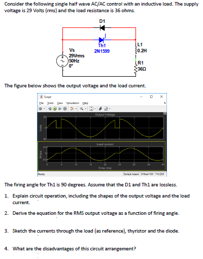
Transcribed Image Text:Consider the following single half wave AC/AC control with an inductive load. The supply
voltage is 29 Volts (rms) and the load resistance is 36 ohms.
D1
L1
0.2H
Th1
Vs
2N1599
29Vrms
50HZ
0°
R1
360
The figure below shows the output voltage and the load current.
E Sope
Ee Icoh yev Seleten bp
Outout Vetoge
Load aurant
Tine (a
Penty
Sample et othe-1 THO2
The firing angle for Thl is 90 degrees. Assume that the D1 and Th1 are lossless.
1. Explain circuit operation, including the shapes of the output voltage and the load
current.
2. Derive the equation for the RMS output voltage as a function of firing angle.
3. Sketch the currents through the load (as reference), thyristor and the diode.
4. What are the disadvantages of this circuit arrangement?
Expert Solution
This question has been solved!
Explore an expertly crafted, step-by-step solution for a thorough understanding of key concepts.

Step by step
Solved in 6 steps with 1 images

Knowledge Booster


Learn more about
Need a deep-dive on the concept behind this application? Look no further. Learn more about this topic, electrical-engineering and related others by exploring similar questions and additional content below.Recommended textbooks for you
Power System Analysis and Design (MindTap Course …
Electrical Engineering
ISBN:
9781305632134
Author:
J. Duncan Glover, Thomas Overbye, Mulukutla S. Sarma
Publisher:
Cengage Learning
Power System Analysis and Design (MindTap Course …
Electrical Engineering
ISBN:
9781305632134
Author:
J. Duncan Glover, Thomas Overbye, Mulukutla S. Sarma
Publisher:
Cengage Learning