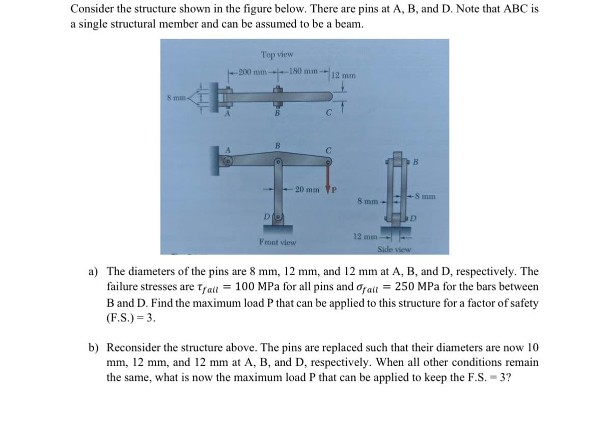
Consider the structure shown in the figure below. There are pins at A, B, and D. Note that ABC is a single structural member and can be assumed to be a beam. 8 mm- Top view 180 mm- -200 mm- D B -20 mm Front view 12 mm C C P 1 8 mm- 12 mm B -8 mm D Side view a) The diameters of the pins are 8 mm, 12 mm, and 12 mm at A, B, and D, respectively. The failure stresses are Tfail = 100 MPa for all pins and of ail = 250 MPa for the bars between B and D. Find the maximum load P that can be applied to this structure for a factor of safety (F.S.) = 3. b) Reconsider the structure above. The pins are replaced such that their diameters are now 10 mm, 12 mm, and 12 mm at A, B, and D, respectively. When all other conditions remain the same, what is now the maximum load P that can be applied to keep the F.S. = 3?
Consider the structure shown in the figure below. There are pins at A, B, and D. Note that ABC is a single structural member and can be assumed to be a beam. 8 mm- Top view 180 mm- -200 mm- D B -20 mm Front view 12 mm C C P 1 8 mm- 12 mm B -8 mm D Side view a) The diameters of the pins are 8 mm, 12 mm, and 12 mm at A, B, and D, respectively. The failure stresses are Tfail = 100 MPa for all pins and of ail = 250 MPa for the bars between B and D. Find the maximum load P that can be applied to this structure for a factor of safety (F.S.) = 3. b) Reconsider the structure above. The pins are replaced such that their diameters are now 10 mm, 12 mm, and 12 mm at A, B, and D, respectively. When all other conditions remain the same, what is now the maximum load P that can be applied to keep the F.S. = 3?

International Edition---engineering Mechanics: Statics, 4th Edition
4th Edition
ISBN:9781305501607
Author:Andrew Pytel And Jaan Kiusalaas
Publisher:Andrew Pytel And Jaan Kiusalaas
Chapter9: Moments And Products Of Inertia Of Areas
Section: Chapter Questions
Problem 9.14P: Compute the dimensions of the rectangle shown in Fig. (b) that has the same kx and ky as the W867...

Related questions

Question
Transcribed Image Text:Consider the structure shown in the figure below. There are pins at A, B, and D. Note that ABC is
a single structural member and can be assumed to be a beam.
8 mm-
A
Top view
-200 mm
B
B
Do
-180 mm-
20 mm
Front view
121
12 mm
CT
C
P
8 mm-
12 mm-
Side view
B
=
-8 mm
D
a) The diameters of the pins are 8 mm, 12 mm, and 12 mm at A, B, and D, respectively. The
failure stresses are Tfail = 100 MPa for all pins and fail 250 MPa for the bars between
B and D. Find the maximum load P that can be applied to this structure for a factor of safety
(F.S.) = 3.
b) Reconsider the structure above. The pins are replaced such that their diameters are now 10
mm, 12 mm, and 12 mm at A, B, and D, respectively. When all other conditions remain
the same, what is now the maximum load P that can be applied to keep the F.S. = 3?
Expert Solution
This question has been solved!
Explore an expertly crafted, step-by-step solution for a thorough understanding of key concepts.

This is a popular solution!

Trending now
This is a popular solution!

Step by step
Solved in 3 steps with 10 images

Knowledge Booster


Learn more about
Need a deep-dive on the concept behind this application? Look no further. Learn more about this topic, mechanical-engineering and related others by exploring similar questions and additional content below.Recommended textbooks for you
International Edition---engineering Mechanics: St…
Mechanical Engineering
ISBN:
9781305501607
Author:
Andrew Pytel And Jaan Kiusalaas
Publisher:
CENGAGE L

Refrigeration and Air Conditioning Technology (Mi…
Mechanical Engineering
ISBN:
9781305578296
Author:
John Tomczyk, Eugene Silberstein, Bill Whitman, Bill Johnson
Publisher:
Cengage Learning
International Edition---engineering Mechanics: St…
Mechanical Engineering
ISBN:
9781305501607
Author:
Andrew Pytel And Jaan Kiusalaas
Publisher:
CENGAGE L
Refrigeration and Air Conditioning Technology (Mi…
Mechanical Engineering
ISBN:
9781305578296
Author:
John Tomczyk, Eugene Silberstein, Bill Whitman, Bill Johnson
Publisher:
Cengage Learning