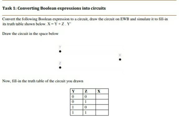
Convert the following Boolean expression to a circuit, draw the circuit on EWB and simulate it to fill-in its truth table shown below. X = Y +Z.Y Draw the circuit in the space below Now, fill-in the truth table of the circuit you drawn Y


Q: Draw the combinational circuit that directly implements the Boolean expression: F(x,y,z)=(x(y XOR…
A: Here is the total three inputs Those are x,y,z And this Boolean expression having y XOR z = y'z+yz'…
Q: A truth table can be implemented with different Boolean expressions and different circuits…
A: Given: A truth table can be implemented with different Boolean expressions and different circuits…
Q: For the circuit shown below, the switch S has been opened for a long time, and at t=0 it is closed.…
A: Answer 1 in(t) = (1 - e(-t/R1C1)) / (120) / (R1/C1) "i..(t) = -120/R2 * (1 - e^(-t/R2C2))"Answer 2…
Q: using Circuit Wizard, please make a simple circuit diagram of Full Subtractor.
A: Block Diagram:-
Q: x(1) - 67 - 4n - 2n 2n 4n 67 Figure 1
A:
Q: B5. Consider the following circuit diagram with three inputs (A, B, C) and one output (X) [4 marks]…
A: Answer to the above question related to boolean expression is in step 2.
Q: Given the below Function: F(x, y, z) = (ỹ +x). (y + z) + xyz a- Draw the combinational circuit that…
A:
Q: QUESTION 18 Simplify the circuit below and write your answer in Boolean algebra M Q
A: Here in this question we have given a booean circuit and we have asked to convert it into boolean…
Q: Draw circuit diagram, Boolean expression of half adder?
A: Half adder The half adder is an electronic circuit that is used to add two binary digits. It takes…
Q: Q2.3 Write the Boolean equation of the logic diagram of the circuit whose outputs are defined by the…
A: Solution:
Q: 2. Consider the Boolean function f(x,y,z) from the given table: f 0. (a) Write the Boolean…
A: Note: - As per the guidelines we can only answer the maximum of three subparts. Please resubmit the…
Q: Then reconstruct the circuit above using
A: Groups (0,1,2,3) A' (0,1,4,5) B' y = A' + B'
Q: Draw a Circuit diagram for the following Expression and write its Truth table. Y = (A B). (A. C) +…
A: Here, Expression is given.
Q: Fill in the blanks to prove that the circuits have the same input/output table by showing that the…
A: Actually, given question regarding Boolean expressions ...
Q: A What boolean expression is equivalent to the circuit presented in the figure? Q = (A and B) or ((B…
A: Inputs: A and B B or C C and B
Q: Build the full-adder circuit using CircuitVerse online circuit simulator, add labels, your name and…
A: Answer: Full-adder circuit using CircuitVerse online circuit simulator: 0 0 0(inputs) = 0 0(outputs)…
Q: Given the below Function: F(x, y, z) = (+ x). (y + z) + xyz a- Draw the combinational circuit that…
A: We have to draw combinational circuit of the given Boolean Expression. what values of x, y, and z…
Q: Complete the following characteristic table for the circuit below: You need explain how you got the…
A: In this question, we have a synchronous sequential circuit. And we have some values at clock 't' and…
Q: A. Write the Boolean equation directly from the following circuit. B. Create the truth table for the…
A: We are given a boolean circuit for which first we will find the logic of the circuit and then we…
Q: What is the Boolean expression for the logic circuit shown? B - O A. ABC + BC +AB О В. АВ + B(В+C) +…
A: EXPLANATION: In the given logic circuit, there is no AND gate that has three inputs, hence ABC…
Q: The logic circuit below is supposed to be designed to produce the truth table also shown below.…
A:
Q: We consider a circuit having four inputs and one output. The output has the value 1 if at least half…
A: 1) Build a truth table for the circuit presented in the description above: Conditions: Output is 1…
Q: Consider the circuit below. Draw the truth table for this circuit, Then, using the Boolean theorems…
A: To draw the truth table for given circuit. And Simplify the expression and redraw the minimal…
Q: What is Clipper? Briefly explain its types with help of circuit diagram.
A: A clipper is a circuit that removes a waveform's peak. A clipper circuit stops a signal from…
Q: Write a MATLAB program to ge the step response and impulse response of the series RLC circuit after…
A:
Q: A. F = xy +x y B. F, = xyz + x y + xy z C. F, = xyw+ x(wz + wz) D. F, = (A+ B) (A+ B) %3D
A: - With the restrictions placed on us because of our guidelines we are allowed to answer the first…
Q: Boolean Logic Draw the truth table for the following functions: F(A,B)=AB+(A+B)…
A: Hey, since there are multiple questions posted, we will answer first question. If you want any…
Q: ounts 0,1,2,3,4) Task 1: (Design the circuit): Write a handwriting report including a short…
A:
Q: BOOLEAN ALGEBRA Experiment #4 Do the lab simulation for the next formula's: 1-(A+B)(A+C) = A+BC 2-…
A: Note: Performing the simulation in python as no language is mentioned. Task : Create the truth…
Q: 8. For the K-map below, ONLY write the simplified expression, and then draw the simplest possible…
A: Please find the simplified expression below
Q: Draw a logic circuit diagram of the below expression. AB'+ BC' it would be great help..if you…
A: The logic circuit diagram for the given expression is shown below - Explanation - There are…
Q: Draw a logic diagram and create a truth table for (a+b) + a(d+b) + a'b'c'
A:
Q: PLEASE EXPLAIN ALL STEPSDraw (hand draw or using an online tool) the circuit diagrams that…
A: The circuit diagrams that correspond to the following Boolean equations drawed using an online tool…
Q: Draw the truth table of the Boolean expression given below: 2. X = A.(B+B')
A: A truth table is a mathematical table used in logic—specifically in connection with Boolean algebra,…
Q: (c) Draw a logic circuit based on Boolean expression below. [Lukiskan sebuah litar logik berdasarkan…
A: I have given logic circuit diagram for the given boolean expression.
Q: Draw the circuit that corresponds to the following Boolean expression: (P ∧ Q)…
A: Circuit is given below :
Q: Draw a circuit diagram for the following truth table. A B C A’ B⊕ C A’(B⊕C) 0 0 0 1 0 0…
A: From the above truth table, we see 3 input symbols, A, B, C. first A complement is performed then…
Q: 2. Draw the truth table of the Boolean expression given below: Y = A.B + A'.B'
A: Given Boolean Expression: Y = A.B + A'.B' Requirement: Draw the truth table of the given expression.…
Q: Draw a logic diagram of your own provided that it has at least three inputs and three gates (NOTs…
A: THE BOOLEAN EXPRESSION OR THE FUNCTION OF THREE GATES IS - In this boolean expression three inputs…
Q: Project Tasks: (attach this page to your report as the front page) Task 1: (Design the…
A: NOTE: ACCORDING TO COMPANY POLICY WE CAN SOLVE ONLY 1 PART PER QUESTION. YOU CAN RESUBMIT THE…
Q: following the 4 steps that we learned in ch4. After
A: Combinational circuit is defined as present output depends only on current inputs There is no…
Q: Write program in e++ language to implement the circuit shown below: D-
A: the following program in c++
Q: Q3: Simplify this expression using Boolean algebra : XYZ + XYZ + XYZ And draw the circuit before and…
A: SIMPLIFICATION: Given, the expression:XYZ+XY¯Z+XYZ¯Now, using the distributive…
Q: Write the Boolean algebra expressions and simplify using Karnaugh map for the following table of…
A: Solution: Here I am using KMAP to simplify the given table: X = A'B + AB' + AC Y = A'B' + BC
Q: .. Write a program in C++ language to find the result of this logic circuit: AB
A: Here we use logic gates AND and Or AND :- A*B A&B OR:- A+B A | B here i provided…
Q: Consider the circuit diagram on the right hand side. Determine a NOR only y representation of this…
A:
Q: ate diagram, function that the circuit perform and revise the circuit by using T Flip lops. SET A…
A:
Q: Write a handwritingreport including a short description about the circuit(including function,…
A: Given:- Write a handwritingreport including a short description about the circuit(including…
Q: Construct the digital circuit with Logisim (or another online simulator) for following expression.…
A: here in given question ask for design a circuit for given logic.
Q: The simplest Boolean expression that can be realised from the Karnaugh Map shown above is A. F=D+BC…
A: Lets se the solution in the next steps


Trending now
This is a popular solution!

Step by step
Solved in 3 steps with 1 images


- A complex _____ expression can be negated using a set of rules known as De Morgan’s laws. Please only fill in lower cases.(Just Words)evelop an algorithm that take two inputs as x and y; and implements the behavior of the following logical circuit. For x = 1 and y =0 show the output in the output window and take a screenshot from your answer beside your flowchart and put it in your report.Draw a finite state machine diagram of a car parking garage that generate a ticket and calculate the price of the parking time till the car get out of garage. (6$ per hour)Also (check if the garage is full or not at the beginning ) (It's a vhdl task)
- This needs to be done in Java Write an application that prints out the temperatures from 0 - 50 degrees Celsius and the converted the Fahrenheit values. Use a while counter controlled loop. Include column headings and correct column spacing. SAMPLE OUTPUT: Celsius Fahrenheit0 32.01 33.82 35.63 37.4Later, the student uses the oscillator to create a single pulse with initial speed vo at at the left end of the string, as shown above. The student wants to quantify the observation that the pulse slows down on the right half of the string. The student comes up with the following equation relating the string’s diameter D at a given point on the string to the speed v of the pulse at that point: v=vo(Do/D) (c) Is the equation consistent with the observation that the pulse slows down on the right half of the string? ____Yes ____No (d) Using frame-by-frame analysis of video of the pulse, the student plots the speed v of the pulse as a function of the string diameter D, as shown below. Are the data in the graph consistent with the student’s equation above? ____Yes ____NoPlease use Scala to solve this question package gatetasks import tinylog._ object factory: /** Returns a gate containing the eXclusive OR of the two input gates */ def buildXOR(in1 : Gate, in2: Gate) : Gate = // TASK 1: Return a gate which contains the exclusive or (XOR) of the two // input gates. // Hints: - Remember that gates can be combined to create new gates using // logic operators || and && and negated using ! // - You can NOT check/compare the .value method of the gates as // values are not set at the time you 'connect' the gates // (remember that you are building a [very small] circuit) // Write your formula here: ??? end buildXOR /** * Returns the majority state of gates in1, in2, in3 */ def buildMajorityOfThree(in1 : Gate, in2 : Gate, in3 : Gate) : Gate = // TASK 2: Return a gate which evaluates to // false - if two or three are false //…
- We have three push button, When the first push button is pressed, the LED is on continuously and when the second push button is pressed, the LED turns on and off, and the last switch turns off the LED program by use arduinoHi, For the solution Can you take a screenshot showing that youare writing and running the code in Matlab/Octave. Write a Matlab/Octave script that takes n as input and print the following pattern For example:If n is 5, the following pattern will be printed.5 4 3 2 14 3 2 13 2 12 11If n is 3, the following pattern will be printed.3 2 12 11GOOD DAY! THIS IS ALL ABOUT THE SUBJECT DISCRETE MATHEMATICS.... AND THE TOPIC IS ALL ABOUT LOGIC OPERATORS. PLEASE ANSWER ONLY PART 3... AGAIN PLEASE ANSWER PART 3 ONLY. PLEASE SEND YOUR SOLUTION ALSO PLEASE