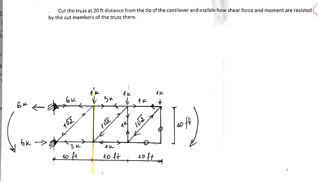
Cut the truss at 20 ft distance from the tip of the cantilever and explain how shear force and moment are resisted by the cut members of the truss there. 3K 102 oft 6K > 3K 1o ft 10 ft


Q: Wo d B C kN/m Answer: Wo
A:
Q: First calculate the section where B.M. is maximum. Where B.M. is maximum, the shear force will be…
A: Given data: Length of beam = 8 m The magnitude of point load =10 kN…
Q: A steel pipe (D = 3.500 in.; d = 3.068 in.) supports a concentrated load of P = 644 lb as shown. The…
A:
Q: Draw shear force digam and bending moment digram for the following beam 300 N 500 N 800 N to to 0.5…
A: A cantilever support will exert horizontal component of reaction, vertical component of reaction and…
Q: Draw Shear and Moment Diagrams for each of the beams below and find max bending stress. Every beam…
A:
Q: Draw the shear and moment diagram of the overhanging beam shown below. For this part, please show…
A: Draw a diagram showing the beam support reactions. Here, RA and RB are the reactions at supports A…
Q: 4) For the beam shown with a rectangular cross-section: a) Draw the shear and moment diagrams (F =…
A:
Q: Draw the axial force, shear force and bending moment diagram for the frame shown in Fig. below. S KN…
A:
Q: Determine the normal force, shear force, and moment at point C of the beam in Figure 3.# 112 kN 9…
A:
Q: Draw the shear force and bending moment diagrams for the loaded beams shown? Explain breifly why the…
A:
Q: 10 kN/m |2m 2m 2m 6m 6m 2. A compound beam is pin connected at E and Fas shown above. a. Determine…
A: For solution refer below images.
Q: 30 kN 50 kN C B 1 m 3 m 2 m
A: Let us consider that the reaction at B is RB and reaction at D be RD . Calculating the reaction at…
Q: A steel pipe (D = 3.500 in.; d = 3.068 in.) supports a concentrated load of P = 500 lb as shown. The…
A:
Q: 6 kN-m 4 kN/m 12 kN A В C E D B 2 m 6 m 2 m
A:
Q: 118,45k 9k ↓ 11' 1k/f 5k in 15,55k
A:
Q: Question 1 Determine the normal force, shear force, and moment at point C of the beam in Figure 1.…
A:
Q: 1. According to the most unfavorable principle, loading the following moment influence line by using…
A: Write the given data. For L0⩽5 then Pk=270 kNFor 5<L0⩽50 m then Pk=2L0+130 kNFor L0≥50 then…
Q: 10. Spar webs develop shear stresses which resist a. Bending shear forced b. Torsional Moment c.…
A: GIVEN DATA A MCQ GIVEN ABOUT SPAR WEB WE HAVE TO CHOOSE CORRECT OPTION
Q: Question 1 Determine the normal force, shear force, and moment at point C of the beam in Figure 1.…
A:
Q: Draw shear and bending moment diagrams for the beamin Figure 3.14b, which carries a uniformly…
A: givencantilever beam as shown below
Q: Situation - Wooden log is used to bridge a 2.5-m gap. The bridge will support a concentrated load of…
A: Length of the bridge, L= 2.5 m= 2500 mm Concentrated load, W=26 kN= 26000 N Allowable bending…
Q: Draw the shear force and the bending moment diagrams for the simply supported beam loaded with a…
A: Shear force diagram represents shear force at every section of the beam. Shear force at any…
Q: A loaded beam, 60 mm wide by 100 mm high and 6 m long, has the shear and moment diagrams as shown…
A: Given: The width of beam, b = 60 mm = 0.06 m The height of beam, h = 100 mm = 0.1 m The length of…
Q: The channel beam with b= 300 mm, h=150 mm, and constant thickness of t=15 mm is subjected to a shear…
A: Given data:- Shear force, V=15 kN
Q: The channel beam with b= 300 mm, h=150 mm, and constant thickness of t=15 mm is subjected to a shear…
A: Given Data:- Magnitude of shear force, V=65 kN
Q: Draw the shear and bending-moment diagrams for the beam AB, and determine the maximum absolute…
A: Draw the free-body diagram of the beam, Now, apply force equilibrium in horizontal direction,…
Q: Problem 5.64 2.5 k/ft Draw the shear, bending moment, and axial force diagrams and the qualitative…
A:
Q: 60 kH 30KN DROW the sheaR and moment Im diagram with complete sokrtion
A: Given: W = 5KN/m
Q: 1. Analyze the statically indeterminate beam by force method, and draw the bending moment diagram,…
A: Let the moment at 1 and 2 is taken as R1 and R2 The degree of static indeterminacy of the beam is…
Q: Draw the shear force and bending moment diagrams for the loaded beams shown? Explain breifly why the…
A:
Q: Q10\ sketch the axial load, shear force and bending moment diagrams. 10KN/m 3im 2 'm 160kN 60KN Į…
A: Reaction force, Ay+Cy=(20×12)+60+60=360 Moment at C pt., ∑Mc=0…
Q: Beam ABCDEFG below is subjected to multiple loads as show. The total length of the beam is 10m.…
A: according to given data
Q: 14.14KN 20KN 40KN-M C20KN/M 1M
A: Shear force diagram represents shear force at every section of the beam. Shear force at any…
Q: PP PL 3P V - 19 PL D. 384 EI
A: given data; ⇒lets take reaction force at A=RA⇒lets take reaction force at point B=RB
Q: Determine the normal force, shear force, and bending moment BY USING THE LEFT SIDE at C of the beam…
A: Weight of the load, W=12×1200×3=1800N it acts 1m from the A points ∑Fx=0RAH=0∑Fy=0RAV=1800N Hence…
Q: 8 ft The cantilevered beam above is subjected to a single point force P = 20 kip at its free end.…
A:
Q: Plot the bending moment ond shear force iagrons. . 9=80000N(m 9,=120000m
A:
Q: 6.43-6.56 Construct the shear force and bending moment diagrams for the beam shown by the area…
A: SFD is one degree higher than the loading diagram and BMD is one degree higher than SFD. If at any…
Q: Pu-250KN Pu-250KN draw shear force and bending moment diagram and With all details ofthe solution…
A: I have made both diagrams clearly and solved the question step by step with each point calculation.
Q: 6.43-6.56 Construct the shear force and bending moment diagrams for the beam shown by the area…
A: Shear force: It is nothing but the force in transverse direction acting on a beam cross-section at…
Q: 5 kN/m |A IC B 3 m Determine the value and direction of the internal normal force, shear force, and…
A: The free body diagram for member ABC is given below,
Q: Draw the shear force and bending moment diagrams for the beam shown. Neglect the weight of the beam.…
A:
Q: The Figure shows a loading set up similar to that of the 'Bending in Beams' laboratory experiment. E…
A:
Q: 10 in 1 in 1 in V 12 in 1 in 5 in The steel wide flange beam shown above is fabricated using three…
A: Given: The first moment of area, A = 27 The centre of gravity from bottom, Yc = 8.204 in The moment…
Q: Draw shear force and bending moment diagram of the beam loaded as shown in the figure. 20 kN 12 kN…
A:
Q: Calculate the internal shear forces and the value of bending moments at points A, D (on member DB…
A:
Q: Cantilever beam loaded as shown in fig., draw the shear force diagram and bending moment diagram. 20…
A:
Q: A girder of I-section has a web 60 cm by 1.25 cm and flanges 30 cm by 2.5 cm. The girder is…
A:
Q: Example 5: Draw the shear force and bending moment diagrams for the simply supported beam as shown…
A:
Q: Draw the shear force and bending moment diagrams for the loaded beams shown? Explain breifly why the…
A: For the given beam Reaction at A = 12.6 kN Reaction at B = 8.4 kN To determine shear force and…

Step by step
Solved in 2 steps with 2 images


- A wood box beam is constructed of two 260 mm × 50 mm boards and two 260 mm × 25 mm boards (sec figure). The boards are nailed at a longitudinal spacing. b = 100 mm. If each nail has an allowable shear force F = 1200 N. what is the maximum allowable shear force Vmax?Two W 310 × 74 Steel wide-flange beams are bolted together to form a built-up beam as shown in the figure. What is the maximum permissible bolt spacing s if the shear force V = 80 kN and the allowable load in shear on each bolt is F = 13.5 kN. Note: Obtain the dimensions and properties of the W shapes from Table F-l(b).A frame ABCD is constructed of steel wide-flange members (W8 x 21; E = 30 x ID6 psi) and subjected to triangularly distributed loads of maximum intensity q0acting along the vertical members (see figure). The distance between supports is L = 20 ft and the height of the frame is h = 4 ft. The members are rigidly connected at B and C. Calculate the intensity of load q0 required to produce a maximum bending moment of 80 kip-in. in the horizontal member BC. If the load q0 is reduced to one-half of the value calculated in part (a), what is the maximum bending moment in member BC? What is the ratio of this moment to the moment of 80 kip-in. in part (a)?
- A cant i levé r b ea m i s supported by a tie rod at B as shown. Both the tie rod and the beam are steel with E = 30 x 106 psi. The tie rod is just taut before the distributed load q = 200 lb/ft is applied. Find the tension force in the tie rod. Draw shear-force and bending-moment diagrams for the beam, labeling all critical ordinates.A loaded beam, 60 mm wide by 100 mm high and 6 m long, has the shear and moment diagrams as shown below. Determine (a) the magnitude, type and location of the maximum flexural stress (in MPa) (b) the stress (specify the type) in a fiber 30 mm from the top of the beam at a section 3.5 m from the left end. I = bh3/12A load of 100 kN, followed by another load of 50 kN, at a distance of 10 metres, advances across a girder with a 100-metre span. Obtain an expression for the maximum bending moment at a section of the girder at a distance of z metres from an abutment. Please provide solutions. Answer is z(140-1.5z) for z< (100/3)m;(100-z)(1.5z-5) for z>(100/3) m.
- Determine the support reactions and Shear force and Bending moment diagram and also determine the point of maximuym shear and Bending moment and their valuesCan you provide me the step by step process of this? Thank you! Use the graphical method to construct the bending-moment diagram and identify the magnitude of the largest moment (consider both positive and negative). The ground reactions and shear-force diagram are provided.MA = 22 kN-mMB = 10 kN-mAy = 17.00 kNBy = 13.00 kNDraw the bending moment and shear diagrams for bar CD of the structure below.
- Engr statics I check it was wrong answer 245.166 I need to show all work. Topic: Shear and Bending Moment A gantry crane of weight W-100 Kg moves across a bridge with the length 1-5 m. The front axle of the crane (which is nearer end A) carries 3/4W whereas the rear axle (nearer end B) carries 1/4 W. The distance of the axles is b = 1/20. Determine the maximum value of the bending moment and enter your answer in N-m units. Remember to also show all your work (FBDs, calculation steps, etc on the handworked file) HINT: Determine the shear and bending moment equationsDraw the shearing-force and bending-moment diagrams for the following beams: 1. A cantilever of length 20 m carrying a load of 10 kN at a distance of 15 m from the supported end. 2. A cantilever of length 20 m carrying a load of 10 kN is uniformly distributed over the inner 15 m of its length. 3. A cantilever of length 12 m carrying a load of 8 kN, applied 5 m from the supported end, and a load of 2kNlm over its whole length.The beam safely supports shear forces and bending moments of 2kN and 6.5 kN-m respectively. Based on this criterion, can it be safely subjected to the loads F = 1kN and C = 1.6 kN-m?