d) To measure currents in the simple circuit shown in Fig. 2 below, you would replace a wire between two points with an ammeter. Specify the points (for example, points aj, ac, etc.) between which you would place an ammeter to measure the following: i. The total current flowing out of the circuit. ii. The current flowing out of R₁. iii. The current flowing into R₂. Neglect any series resistances of the wires used for the connections in the circuit. V. V vi. vii. C a R₁ 2 R₂ The potential difference across R₁. The potential difference across R3. The potential difference across R4. R3 R₁ d g Fig. 2. Sir electrical circuit Specify, also, from the Fig., the points to which you would connect a voltmeter to measure the following potential differences in the circuit: iv. The potential difference of the voltage source. n
d) To measure currents in the simple circuit shown in Fig. 2 below, you would replace a wire between two points with an ammeter. Specify the points (for example, points aj, ac, etc.) between which you would place an ammeter to measure the following: i. The total current flowing out of the circuit. ii. The current flowing out of R₁. iii. The current flowing into R₂. Neglect any series resistances of the wires used for the connections in the circuit. V. V vi. vii. C a R₁ 2 R₂ The potential difference across R₁. The potential difference across R3. The potential difference across R4. R3 R₁ d g Fig. 2. Sir electrical circuit Specify, also, from the Fig., the points to which you would connect a voltmeter to measure the following potential differences in the circuit: iv. The potential difference of the voltage source. n

Introductory Circuit Analysis (13th Edition)
13th Edition
ISBN:9780133923605
Author:Robert L. Boylestad
Publisher:Robert L. Boylestad
Chapter1: Introduction
Section: Chapter Questions
Problem 1P: Visit your local library (at school or home) and describe the extent to which it provides literature...

Related questions

Question
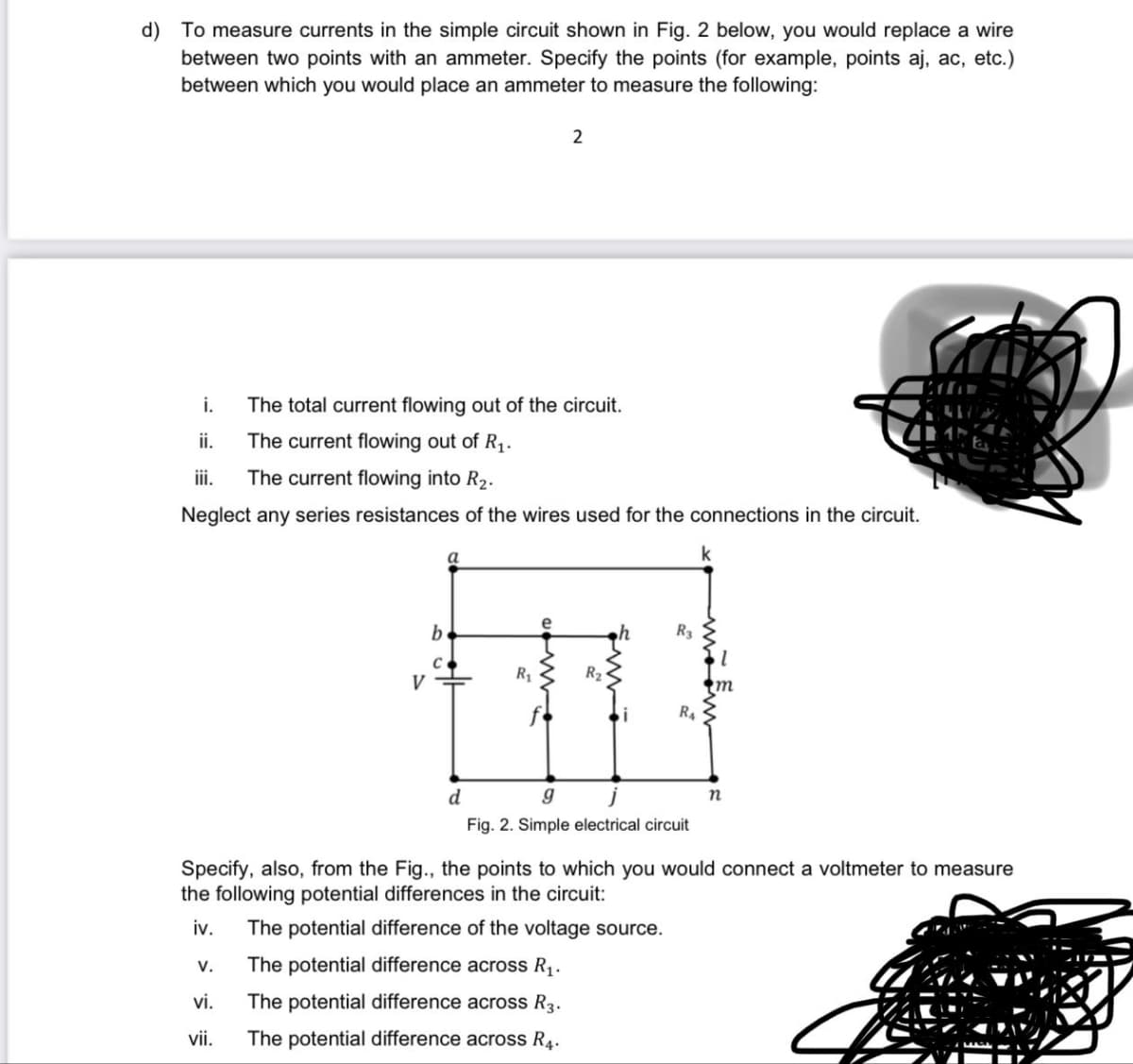
Transcribed Image Text:d) To measure currents in the simple circuit shown in Fig. 2 below, you would replace a wire
between two points with an ammeter. Specify the points (for example, points aj, ac, etc.)
between which you would place an ammeter to measure the following:
i.
The total current flowing out of the circuit.
ii.
The current flowing out of R₁.
iii.
The current flowing into R₂.
Neglect any series resistances of the wires used for the connections in the circuit.
V.
V
vi.
vii.
C
a
2
R₁
R₂
R3
R₁
d
g
Fig. 2. Sir electrical circuit
Specify, also, from the Fig., the points to which you would connect a voltmeter to measure
the following potential differences in the circuit:
iv. The potential difference of the voltage source.
The potential difference across R₁.
The potential difference across R3.
The potential difference across R4.
n
Expert Solution
This question has been solved!
Explore an expertly crafted, step-by-step solution for a thorough understanding of key concepts.

Step by step
Solved in 2 steps with 1 images

Knowledge Booster


Learn more about
Need a deep-dive on the concept behind this application? Look no further. Learn more about this topic, electrical-engineering and related others by exploring similar questions and additional content below.Recommended textbooks for you
Introductory Circuit Analysis (13th Edition)
Electrical Engineering
ISBN:
9780133923605
Author:
Robert L. Boylestad
Publisher:
PEARSON

Delmar's Standard Textbook Of Electricity
Electrical Engineering
ISBN:
9781337900348
Author:
Stephen L. Herman
Publisher:
Cengage Learning

Programmable Logic Controllers
Electrical Engineering
ISBN:
9780073373843
Author:
Frank D. Petruzella
Publisher:
McGraw-Hill Education
Introductory Circuit Analysis (13th Edition)
Electrical Engineering
ISBN:
9780133923605
Author:
Robert L. Boylestad
Publisher:
PEARSON
Delmar's Standard Textbook Of Electricity
Electrical Engineering
ISBN:
9781337900348
Author:
Stephen L. Herman
Publisher:
Cengage Learning
Programmable Logic Controllers
Electrical Engineering
ISBN:
9780073373843
Author:
Frank D. Petruzella
Publisher:
McGraw-Hill Education

Fundamentals of Electric Circuits
Electrical Engineering
ISBN:
9780078028229
Author:
Charles K Alexander, Matthew Sadiku
Publisher:
McGraw-Hill Education

Electric Circuits. (11th Edition)
Electrical Engineering
ISBN:
9780134746968
Author:
James W. Nilsson, Susan Riedel
Publisher:
PEARSON

Engineering Electromagnetics
Electrical Engineering
ISBN:
9780078028151
Author:
Hayt, William H. (william Hart), Jr, BUCK, John A.
Publisher:
Mcgraw-hill Education,