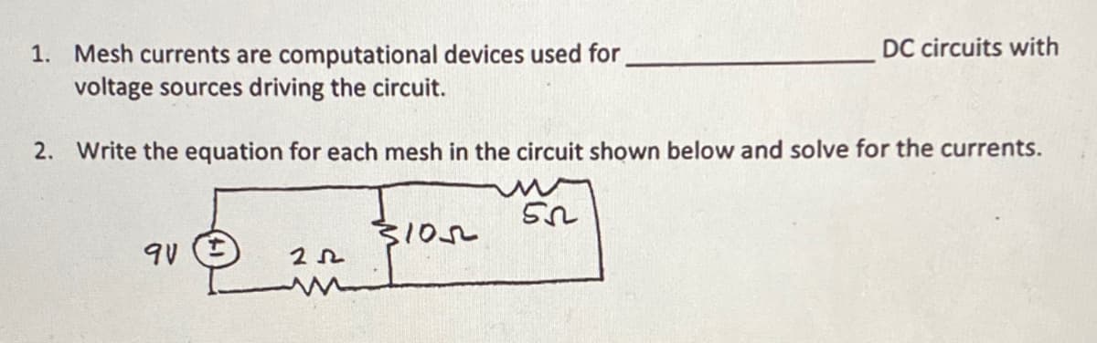
DC circuits with 1. Mesh currents are computational devices used for voltage sources driving the circuit. 2. Write the equation for each mesh in the circuit shown below and solve for the currents. 3102


Q: 5. Determine the mesh currents i, , i, and i, in the circuit below.
A:
Q: 4. Find I, and R, for the circuit below
A:
Q: Consider the following circuit. Given that the voltage source generates 8 W, R1 absorbs 1 W, R2…
A: Concept of Parallel Circuit: In Parallel Connection the positive terminal of all the elements are…
Q: R2 Rs Find the Norton equivalent of given circuit by using nodal analysis. Voltage Source= V. It has…
A:
Q: Find the equivalent resistence that is seen by the 20 V source in the circuit shown to the right,…
A: The equivalent resistance is calculated by start reducing from left to right by taking series and…
Q: (c) Now consider the circuit components to have the following values: R1 =2 Q, R2 = 4 2, R3 = 1 2,…
A:
Q: Using nodal analysis, find the voltage, V, and current, I in the circuit below.
A:
Q: 1. Draw the Norton equivalent for the circuit given. For the looking back Resistance, Ro (express…
A:
Q: Using Mesh-Current analysis, determine the voltages VA, VB, and VC in the circuit below. Also…
A:
Q: True fales Thévenin's theorem states the following: Any two- terminal dc network can be replaced by…
A: ELECTRICAL NETWORK: When addressing a circuit problem or constructing a balanced circuit, the word…
Q: Find the current i in the circuit below using basic techniques such as KVL, KCL, and Ohm's law. Then…
A:
Q: Consider the following circuit in which V1 = 16 V, I1 = 8 A, R1 = 7 Ω, R2 = 5 Ω, R3 = 19 Ω, What is…
A: To find the thevenin;s resistance, short circuit the voltage source and open circuit the current…
Q: 1.Use the node-voltage method of circuit analysis to find the branch currents ia, ib, and ic in the…
A: Applying KCL at node VA
Q: Use Thevenin’s Theorem to determine the current I flowing in the 3 ohms resistor shown in the…
A:
Q: Consider a series-parallel circuit below with the given following resistances are Rq= 10 ohms, R2=…
A: In the circuit, resistor “R2” and resistor “R3” are connected in parallel and the parallel…
Q: R,=0.1 2 120 V { R, = 15 1
A: Circuit is given as,
Q: Compute for the current i1 in the circuit shown below.
A: Given
Q: For the given circuit, the voltage V = 52 V and resistance R, = 300 0. 1 250 2 V When the switch is…
A:
Q: Write the mesh-current equations for the network shown below. b) Determine the mesh currents. c)…
A: Hindi question we need to find a Mesh equation and it's value and the node voltage
Q: When the mesh-current method is applied to a circuit with a dependent voltage source, how is this…
A: Answer: (B) Explanation: For handling of such circuits no special treatment is required. All mesh…
Q: 3. a)_Use the mesh-current method to write a complete set of independent equations that could be…
A: The given circuit after assigning all the currents is as shown below,
Q: Q2) For the circuit shown in figure Q2, use nodal analysis to calculate the current []. Also find…
A:
Q: electronics circuit about? What's the purpose of this circuit and how can this circuit be used in…
A:
Q: В |C D The branch currents h, 2, 3, and l4 are А, A, A, and |A, respectively.
A: The given circuit with proper markings can be drawn as: According to KCL Sum of incoming…
Q: the current passing through 1kΩ by applying the Mesh Analysis method.
A:
Q: Use the mesh current method to find the power developed in the dependent voltage source, voltage…
A:
Q: 2- For the circuit in procedure, apply the Thevenin's theorem tcalculate theoretically the current…
A: Thevenin's Theorem states that “Any linear circuit containing several voltages and resistances can…
Q: 1- For a series RL circuit supplied from a voltage source, discuss in details how the resistance…
A: We’ll answer the first question since the exact one wasn’t specified. Please submit a new question…
Q: 4. a) Use the mesh-current method to write a complete set of independent equations that could be…
A: The circuit is assigned with current variables as shown below,
Q: VI R1 R3 RL R2 För the above circuit, given that V = 30 Volts, %3D h = 28 Amps, %3D R1 5 Ohms, R2 =…
A: Given
Q: Please solve briefly i) Describe the steps to determine the mesh currents in Mesh Analysis. ii)…
A:
Q: Derive a formula relating V, to V, and V, for the following circuit:-
A: To answer above question, one should know what an amplifier is. An amplifier is an electronic…
Q: Determine the equivalent resistance, Rab, of the circuit shown in the figure.
A: By looking at the figure: Potential b is equal to potential e., so simplify the circuit. b=e Redraw…
Q: 6. a) Use the mesh-current method to write a complete set of equations that could be used to solve…
A: Mesh Analysis: Mesh analysis is also known as the mesh current method. It is a method for solving…
Q: Q2. The mesh currents are labeled in the circuit shown in the figure. Determine the value of the…
A: Given,
Q: Calculate the resistance that RL must have, so that the maximum power transfer occurs (obtaining…
A:
Q: Obtain the current flowing in the circuit in resistance(22) with Nodal Analysis Techniques.
A: For given circuit, converting current source to voltage source first
Q: For the circuit in the given figure, use KCL to find the branch currents /4 to l4. Assume A = 6 A, B…
A: Given data, A=6 A, B =7 A, C=5 A, D=6 A. Circuit diagram is given,
Q: For the given circuit, the voltage V = 56 V and resistance R2 = 370n. 100 2 R: 2 When the switch is…
A:
Q: "NODAL VOLTAGE ANALYSIS" Please Find the Vo Using NODAL VOLTAGE ANALYSIS thankyou very much! I've…
A:
Q: Find the Thevenin Equivalent of the circuit below. List the Open Circuit Voltage, Short Circuit…
A:
Q: 0.2 For the circuit shown; Find the source voltage (V) and the total resistance (Req) of the circuit…
A: Given, current flows through resistor 9 ohm is 3 A.
Q: Reduce the circuit so that when using nodal analysis, four node voltages will be solved. What are…
A:
Q: Practice problem 3.1: Find the voltages at the three nonreference nodes in the circuit of Figure…
A:
Q: Q2) For the circuit shown, calculate the: a) Total current flowing through the two supplies. 22k b)…
A: Fig: Given circuit (A) Calculate Req across terminal x and y R1=3∥6R1=3×63+6 R1=2…
Q: the mesh-current method to solve for v in the circuit below, Give our answer in Volts (V).
A: In the above the circuit assume zero voltage at lower end of the circuit. And use the mesh current…
Q: Find the Thevenin Equivalent of the circuit below. List the Open Circuit Voltage, Short Circuit…
A:
Q: HW//1- For the circuit shown below, find the value V, ,and V2. 30V • 20 v-
A: We need to apply kvl to get V1 and V2.
Q: Solve current l, in the circuit below using Thevenin's Theorem. If the circuit diagram below is not…
A:

Step by step
Solved in 2 steps with 1 images

- Complete the table and give the step-by-step solution.The electric current I in a circuit shown in the figure was measured as a function of theresistance R in the circuit. The relationship between I and R is given by? =?? + ?where ? is the emf of the battery in the circuit and r is the internal resistance of the battery. where ? is the emf of the battery in the circuit and r is the internal resistance of the battery.a) Linearise the equation above, and state which variable you would plot on the x-axis andwhich on the y-axis.b) How are ? and r related to the gradient and/or y-intercept of the graph?The electrical model of a biopotential electrode is given belowwith the given values. (a)Plot the absolute impedance of this electrode(i.e.,|Z|) with respect to the frequency using a python script and (b) discuss the frequency range to reachthe minimum absolute impedance value on this electrode. Rd:26 kΩ Rs: 6 kΩ
- Nodal analysis is another very useful way to obtain information regarding a circuit.electric. For example, consider the 4 Ω resistor in the circuit shown below. Nodal tension to your left was named V1, while the right was named V2. Therefore, determine the values of these tensions. answer:v1 = 9,43 V ; v2 = 11,15 VConsider the interconnection shown 1. What value of v1 is required to make this a valid interconnection?2. For this value of v1, find the power associated with the voltagesource.Bioelectrical impedance analysis is a commercially available method used to estimate body fat percentage. The device applies a small potential between two parts of the patient's body and measures the current that flows through. With an estimate of the resistance individually of the muscle and fat between the two points, the composition of the tissue can be estimated. Assume that the muscle and fat tissue can be modeled as resistors in parallel. a) If a potential difference of 5 V is applied across the patient's arm, what is the potential drop across the patient's fat? b) If the measured resistance of the patient's arm is 750 Ω and the resistance of fat is 3 times that of muscle, what is the resistance of the muscle?
- A solar cell with a reverse saturation current of 5 nA is illuminated such that the short-circuit current is Isc = 200 mA.a. Plot I-V and obtain the voltage at maximum delivered power.b. Assume that this cell has a series resistance of 1 Ohm, so that the cell voltage is reduced by the IR drop. Replot the I-V curve for this case and compare with the plot in a.a. Find the total resistance across the terminals at points a and b. b. If a variable DC power supply is connected to terminals ab and its output voltage will beslowly increased, which among the resistors is first to fail. (Assume that the DC power supply canoutput 0 to infinity V DC and can supply the current needed by the given circuit as its output voltageis increased).Subject: CircuitsShow your solution and circuits diagram
- Vbatt=25 VC1=90 ?CC2=75 ?CC3=60 ?CR1=160 ΩR2=120 Ωt2=21.6 msect3=27 msecConsider the circuit shown below which shows a battery connected to some resistors and capacitors along with some switches which will be toggled opened or closed at different times. The components are listed above. The capacitances are in microCoulombs (?C), the resitances are in Ohms (Ω), and the times are in milliseconds (msec). A stopwatch is started at time t1=0 ms. At that time, switch S1 is closed and all other switches are open and the capacitor is allowed to charge up.(a). What is the charge (in uC) on C1 at the time the stopwatch reads t2=21.6 ms?Ans: 1750 uC(b). What is the current (in mA) through R1 at t2=21.6 ms?Ans: 34.9 mA(c). What is the voltage (in V) across R1 at t2=21.6 ms?Ans: 5.58 V(d). What is the voltage (in V) across C1 at t2=21.6 ms?Ans: 19.4 V(e). What is the energy (in mJ) in C1 at t2=21.6 ms?Ans: 17.0 mJThen, immediately at time t2=21.6 on the stopwatch, switch S1 is thrown open and…Vbatt=25 VC1=90 ?CC2=75 ?CC3=60 ?CR1=160 ΩR2=120 Ωt2=21.6 msect3=27 msecConsider the circuit shown below which shows a battery connected to some resistors and capacitors along with some switches which will be toggled opened or closed at different times. The components are listed above. The capacitances are in microFarads (?F), the resitances are in Ohms (Ω), and the times are in milliseconds (msec). A stopwatch is started at time t1=0 ms. At that time, switch S1 is closed and all other switches are open and the capacitor is allowed to charge up.(a). (i)What is the charge (in uC) on C1 at the time the stopwatch reads t2=21.6 ms?a)3690 b)1520 c)5710 d)2630 e)683 f)1750 (a).(ii)What is the current (in mA) through R1 at t2=21.6 ms?34.9 30.4 114 13.6 73.6 52.4 (b)(i)What is the voltage (in V) across R1 at t2=21.6 ms?8.37 5.58 2.18 11.8 18.2 4.85(ii). What is the voltage (in V) across C1 at t2=21.6 ms?63.2 29.1 40.9 7.57 19.4 16.9(c). (i) What is the energy (in mJ) in C1 at t2=21.6 ms?6.63…Compute for IN, RN and the current passing though the 25-ohm resistor using Norton’s Theorem. Answer neatly and please explaiin the process