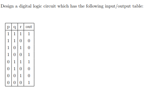
Design a digital logic circuit which has the following input/output table: Parout 111 1 1100 101 100 0|11 1 0 100 001 00l0 1


Q: A: Design an arithmetic circuit with one selection variable S and two n-bit data inputs A and B. The…
A: A: Design an arithmetic circuit with one selection variable S and two n-bit data inputs A and B. The…
Q: Given a 100-MHz clock signal, construct a circuit using T flip-flops to generate 50-MHz and 25-MHz…
A: A T-Flip-Flop (TFF) is basically a clock divide by two. Feed one a 100 MHz clock and you get out a…
Q: SECTION D: DIGITAL LOGIC 1. Draw the logic circuit represented by the following expression: a)…
A: Logic Circuit is the pictorial representation of the Boolean expressions. Each logical operation is…
Q: A combinational logic circuit has three inputs with sequence A, B, and C and two outputs with…
A: 1. Boolean Algebra – This forms the algebraic expression showing the operation of the logic circuit…
Q: Design a logic circuit that detect the prime number in 4-bits binary input number
A: Lets see the solution.
Q: Answer this question, part (1), (2) & (3). Design a combinational logic circuit that converts a…
A:
Q: A combinational logic circuit has one output (F) and four inputs (a, b, c, and d). The circuit is…
A: Static one hazard can be detected using the following steps: Step-1: We draw the k-map using the…
Q: Q2) Design a logic circuit that detects the inputs divisible by 2 or 3 in 4-bit data (0 is divisible…
A: Let's start with the assuming the 4-bit number as ABCD (0000-1111) with 1st bit as A. Now, except 1,…
Q: Design a logic circuit to implement the operation specified in the truth table given below. Truth…
A:
Q: Draw the circuit diagram of the following expression. (A+B+C)DE a) Also Implement the above…
A: Please refer below for your reference: a):
Q: :Design a 3 bits binary synchronous counter with JK flip-flops. That count the odd numbers.
A: Course: Logic Circuit Design Design a 3 bits binary synchronous counter with JK flip-flops. That…
Q: A'- B DI -D- B' The Boolean expression for the above logic circuit is O a. F = (A' + B) + (B' +C) O…
A: It is based on computer architecture.
Q: Design a sequential circuit that detects the serial input sequence of '10011'. And implement the…
A: I have provided solution in step2
Q: Find the nodal voltages of the circuit shown below. 2 Ohms 101 5 Ohms V 15 Ohms 20 Ohms 4 Chms 10…
A:
Q: Design a NAND Logic Circuit that is equivalent to the AOI circuit shown below: A B C D-z =BC +AC
A: Given logic circuit contains NOT, AND and OR gates. Given function is, Z=BC+AC
Q: Design an arithmetic circuit with one selection variable S and two n-bit data inputs A and B. The…
A: Answer: Arithmetic circuit: The design of an arithmetic circuit with the selection variable S and…
Q: 1. Design a logic circuit that has 3 inputs A, B, and Cand one output F. The output of the circuit…
A:
Q: Design a clocked sequential circuit that recognizes the 4-bit input sequence 1010, including overlap…
A: Answer:-
Q: Design an equivalent logic circuit for the 4-bit Arithmetic and Logic Unit
A: Combinational Circuits Multiplexer (IC NO – 74151) The multiplexer or MUX is a virtual switch, also…
Q: i) Design a 2- bit magnitude comparator ii)Design a combinational logic circuit to add two BCD…
A: i) 2-BIT MAGNITUDE COMPARATOR- 2-Bit Magnitude Comparator Compares two numbers each having two bits…
Q: Question 1 Design a circuit to input number X (3 bit) and output (X-1) if X is odd and (X+5) if X is…
A: Given that, For the three bit input number X, if the input is odd number then the output is X-1 and…
Q: In sequential logic circuit, the outputs depend on The inputs and the previous output Oa. Ob. The…
A: Below is the correct answer for the given MCQ question:
Q: DIGITAL LOGIC DESIGN: Add the following unsigned binary numbers. (11010011)2 & (11101110)2
A: Given: DIGITAL LOGIC DESIGN: Add the following unsigned binary numbers. (11010011)2 &…
Q: (a) Perform the following binary additions. (i) 110111 + 11010 (ii) 101101.101 + 101011.011 (iii)…
A:
Q: a. Design the circuit with one-hot state encoding. b. Design the circuit with 3-bit Johnson…
A: Answer is given below .
Q: Design a logic circuit whose input is 1100100000 and the output is 110010
A: Hey there, I am writing the required solution of the above stated question.Please do find the…
Q: Design a combinational circuit that multiplies two 2-bit numbers ala0 and b1b0 to produce a 4-bit…
A:
Q: Design a combinational circuit that accepts a 4-bit number and generates a 3-bit binary number…
A: Sequential model: This NAND gate is a physical circuit during which the output is determined by the…
Q: Design a combinational logic circuit to find 1s complement for a binary number of 4 bit.
A:
Q: The negative numbers are stored in a computer as 2's complement form plus 1. * False Skip True The…
A: Given To know about the 1) negative numbers are stored in a computer as 2's complement plus one .…
Q: Design a combinational circuit that multiplies two unsigned 2-bit numbers, A1 A0 and B1 B0 to…
A:
Q: For the state diagram shown below write the state table and design logic circuit 0/0 001 0/0 1/1 1/0…
A: Given:
Q: Q3.Convert the logic diagram of the circuit shown in the Figure into a multiple-level NAND circuit.…
A:
Q: wo's complement of a number any of four bits usi
A: Q. Design a combinational circuit that calculates the two's complement of a number any of four…
Q: QI) Design a combinational circuit with three inputs, A, B and Outputs, X,Y and Z. when the binary…
A: Truth Table is A B C X Y Z 0 0 0 0 1 0 0 0 1 0 1 1 0 1 0 1 0 0 0 1 1 1 0 1 1 0 0 1 1 0…
Q: 3. Draw an alternate logic symbol sometimes used to show a NAND gate (has inverted inputs). 4. Draw…
A: NAND gate can be formed with the help of NOR gate:
Q: When an input electrical signal A=10100 is applied to a NOT gate, its output signal is A 01011 B…
A: NOT gate is nothing but inverting 0's to 1's and 1's to 0's
Q: For the circuit shown below, find the value of V. 741 Vo 1 mA Color code for resistors: 12 345 6 789…
A: IC 741 is an operational amplifier integrated circuit which have a wide range of application in…
Q: Design a combinational logic circuit that Subtractor (B8 B7 B6 B5 B4 B3 B2 B1) from (A8 A7 A6 A5 A4…
A: The 8 bit subtractor is used to subtract two 8 bit binary numbers. Given two 8 bit binary numbers…
Q: let consider 5 different outputs in combinational circuit/ Digital Logic Design For example x=1 y=…
A: We need to design a single output schema which take the 5 different outputs into a single 5 bit…
Q: 1) Design an arithmetic circuit with one selection variables and two n-bit data inputs A and B. The…
A:
Q: Design an arithmetic circuit with one selection variable S and two n-bit data inputs A and B. The…
A:
Q: Design a sequential circuit that detects the serial input sequence of '10010'. And implement the…
A: Answer: Sequence - 10010 input=x output=z Example: input x 0010010010100100 output z…
Q: (a )Design a 2-bit counter circuit using J-K Flip-flops
A: Q3)b)A 2-bit counter circuit using J-K flip-flops
Q: A circuit's transition diagram is given in the Figure 1; a. Design the circuit with binary state…
A: The complete answer is given below.
Q: IV. COMBINATIONAL LOGIC GATES INSTRUCTIONS: DETERMINE THE OUTPUTS OF THE GIVEN FIGURES. FILL IN THE…
A: For output of x1, We just calculate XOR gate for value of A and B. Because C and D are not connected…
Q: Design a combinational circuit that multiplies two 2-bit input binary numbers; X & Y; and outputs…
A: A circuit formed by combination of different logic gates is called as combinational circuits. The…
Q: Design a combinational circuit using a Decoder and OR gates. The circuit accepts a 2-bit number and…
A: Required: Design a combinational circuit using a Decoder and OR gates. The circuit accepts a…
Q: Design a combinational circuit with three inputs A, B, & C. The output Z is HIGH when the binary…
A: Truth table A B C Z 0 0 0 0 0 0 1 0 0 1 0 0 0 1 1 0 1 0 0 1 1 0 1 0 1 1 0 1 1 1 1…

Step by step
Solved in 2 steps with 2 images


- Design a logic circuit to implement the operation specified in the truth table given below. Truth table INPUT Output Product Term ABC X 000 001 010 011 100 101 110 111 0 0 0 1 0 1 1 0 A’BCAB’C ABC’Design a combinational logic circuit that takes a 3–bit input and has one output P. The P output should be active high only when the inputs corresponds to a prime number Note: the prime numbers: Prime numbers are 2, 3, 5, 7… Select one: a. P= AC+B b. P= A'C+A'B c. P= AC+A'B d. P= AC+A'B'Design a combinational circuit that calculates the two's complement of a number any of four bits using only logic gates
- Find the digital logic circuit output Y as shown above. Y is the output and the three inputs are A, B and C.Identify the state diagram operation and find its output sequence for the following input sequence X=0101-1100-101-0000 the circuit accepts input bits from LSB to MSBA 1bit 4 to 1 multiplexer, the 4 inputs of the multiplexer will be the output of another combinational circuit with A and B as an input:00 = 1bit Adder01 = 1bit Subtractor10 = 1bit Comparator (equals)11 = XOR • truth table• Boolean Expression• Logic Circuit Here is the truth table guide:
- Course: Logic Circuit Design Q:Design a 3 bits binary synchronous counter with JK flip-flops. That count the odd numbers.Find the digital logic circuit output Y as shown above. Y is the output and the three inputs are A, B and C. ComputerDesign a synchronous sequential logic circuit that counts through the repetitive binary sequence 101, 111, 010, 100, 000, 001, 011, 101, etc. Implement your design using the JK- flip flops and a minimum number of logic gates
- design and implement a combinational logic circuit that adds binary numbers and acircuit that will multiply a 2-bit number by a 2-bit numberDesign a combinational circuit with three inputs A, B, & C. The output Z is HIGH when the binary value of the inputs is an EVEN number and is greater than TWO. Draw the circuit using ONLY NOR gates.let consider 5 different outputs in combinational circuit/ Digital Logic Design For example x=1 y= 0 a =1 b= 1 c=0 Design a single output schema which take the 5 different outputs into a single 5 bit output Y[4:0] Y output will be for example 5 bits 10110