Design a voltage divider bias network as shown in Figure Qa using resistor nearest preferred values (NPV) with the following parameters: Vcc = 15 V, lcat = 5 mA, lca = 0.5 lcat, and B = 100. Vcc Rc o Vo R = SKO R 2KO Z. Figure Qa Stating all assumptions made, calculate: i) ii) all the resistor values R, R2, RE, and Rc the emitter current, lE re ww ww
Design a voltage divider bias network as shown in Figure Qa using resistor nearest preferred values (NPV) with the following parameters: Vcc = 15 V, lcat = 5 mA, lca = 0.5 lcat, and B = 100. Vcc Rc o Vo R = SKO R 2KO Z. Figure Qa Stating all assumptions made, calculate: i) ii) all the resistor values R, R2, RE, and Rc the emitter current, lE re ww ww

Power System Analysis and Design (MindTap Course List)
6th Edition
ISBN:9781305632134
Author:J. Duncan Glover, Thomas Overbye, Mulukutla S. Sarma
Publisher:J. Duncan Glover, Thomas Overbye, Mulukutla S. Sarma
Chapter3: Power Transformers
Section: Chapter Questions
Problem 3.30P: Reconsider Problem 3.29. If Va,VbandVc are a negative-sequence set, how would the voltage and...

Related questions
Question
Transcribed Image Text:a)
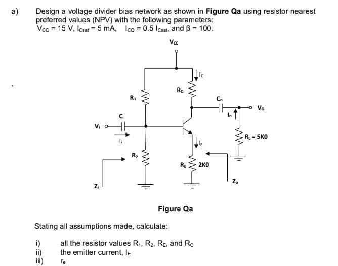
Design a voltage divider bias network as shown in Figure Qa using resistor nearest
preferred values (NPV) with the following parameters:
Vcc = 15 V, Icsat = 5 mA, Ica = 0.5 losats and B = 100.
Vcc
Rc
R1
Co
o Vo
la
R = 5KO
li
R2
2KO
Za
Figure Qa
Stating all assumptions made, calculate:
i)
ii)
ii)
all the resistor values R1, R2, RE, and Rc
the emitter current, le
re
ww
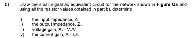
Transcribed Image Text:b)
Draw the small signal ac equivalent circuit for the network shown in Figure Qa and
using all the resistor values obtained in part b), determine
i)
the input impedance, Zi
the output impedance, Z,
ii)
i)
voltage gain, A, =VNi
iv)
the current gain, A = l/li
Expert Solution
This question has been solved!
Explore an expertly crafted, step-by-step solution for a thorough understanding of key concepts.

Step by step
Solved in 3 steps with 4 images

Knowledge Booster


Learn more about
Need a deep-dive on the concept behind this application? Look no further. Learn more about this topic, electrical-engineering and related others by exploring similar questions and additional content below.Recommended textbooks for you
Power System Analysis and Design (MindTap Course …
Electrical Engineering
ISBN:
9781305632134
Author:
J. Duncan Glover, Thomas Overbye, Mulukutla S. Sarma
Publisher:
Cengage Learning

Delmar's Standard Textbook Of Electricity
Electrical Engineering
ISBN:
9781337900348
Author:
Stephen L. Herman
Publisher:
Cengage Learning
Power System Analysis and Design (MindTap Course …
Electrical Engineering
ISBN:
9781305632134
Author:
J. Duncan Glover, Thomas Overbye, Mulukutla S. Sarma
Publisher:
Cengage Learning
Delmar's Standard Textbook Of Electricity
Electrical Engineering
ISBN:
9781337900348
Author:
Stephen L. Herman
Publisher:
Cengage Learning