Design of an AC-AC Converter. The Circuit Below shows a single-phase AC voltage controller with a, a 20:1 step down transformer. The delay angle of thyristor is 45 degrees. The Load is chosen according to the Following: RL= (20 + 0.2 * 17) Q L1 = (50- 0.2 * 17) mH mH Calculate the Following: D2 D1 V1 L1 120Vrms C1 60HZ 0° RL
Design of an AC-AC Converter. The Circuit Below shows a single-phase AC voltage controller with a, a 20:1 step down transformer. The delay angle of thyristor is 45 degrees. The Load is chosen according to the Following: RL= (20 + 0.2 * 17) Q L1 = (50- 0.2 * 17) mH mH Calculate the Following: D2 D1 V1 L1 120Vrms C1 60HZ 0° RL

Power System Analysis and Design (MindTap Course List)
6th Edition
ISBN:9781305632134
Author:J. Duncan Glover, Thomas Overbye, Mulukutla S. Sarma
Publisher:J. Duncan Glover, Thomas Overbye, Mulukutla S. Sarma
Chapter3: Power Transformers
Section: Chapter Questions
Problem 3.63P: A 23/230-kV step-up transformer feeds a three-phase transmission line, which in turn supplies a...

Related questions

Question
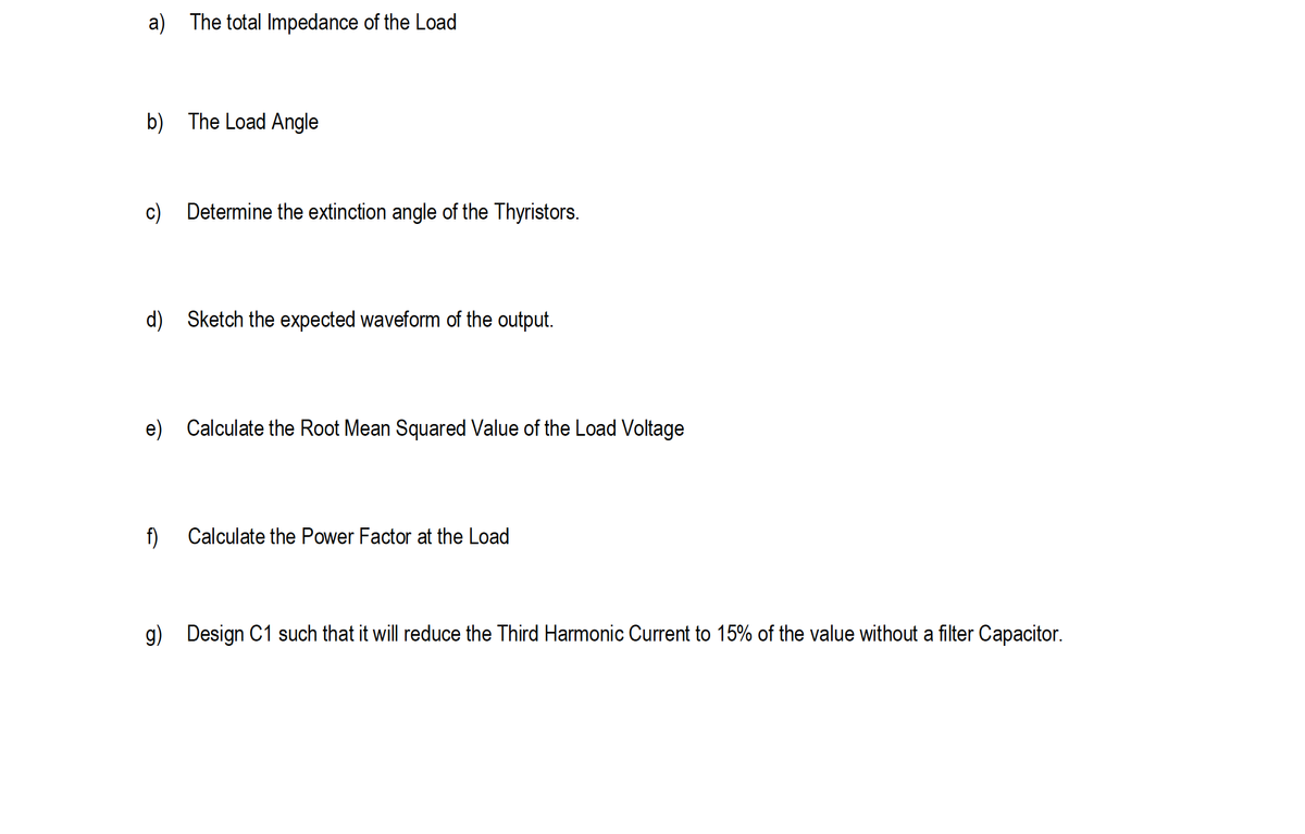
Transcribed Image Text:a) The total Impedance of the Load
b) The Load Angle
c) Determine the extinction angle of the Thyristors.
d) Sketch the expected waveform of the output.
e) Calculate the Root Mean Squared Value of the Load Voltage
f)
Calculate the Power Factor at the Load
g) Design C1 such that it will reduce the Third Harmonic Current to 15% of the value without a filter Capacitor.
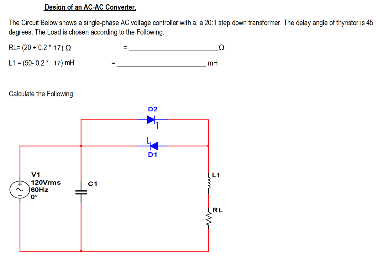
Transcribed Image Text:Design of an AC-AC Converter.
The Circuit Below shows a single-phase AC voltage controller with a, a 20:1 step down transformer. The delay angle of thyristor is 45
degrees. The Load is chosen according to the Following:
RL= (20 + 0.2 * 17) Q
Ω
L1 = (50- 0.2 * 17) mH
mH
%D
Calculate the Following:
D2
D1
V1
L1
120Vrms
C1
60HZ
0°
RL
Expert Solution
This question has been solved!
Explore an expertly crafted, step-by-step solution for a thorough understanding of key concepts.

This is a popular solution!

Trending now
This is a popular solution!

Step by step
Solved in 2 steps with 2 images

Knowledge Booster


Learn more about
Need a deep-dive on the concept behind this application? Look no further. Learn more about this topic, electrical-engineering and related others by exploring similar questions and additional content below.Recommended textbooks for you
Power System Analysis and Design (MindTap Course …
Electrical Engineering
ISBN:
9781305632134
Author:
J. Duncan Glover, Thomas Overbye, Mulukutla S. Sarma
Publisher:
Cengage Learning
Power System Analysis and Design (MindTap Course …
Electrical Engineering
ISBN:
9781305632134
Author:
J. Duncan Glover, Thomas Overbye, Mulukutla S. Sarma
Publisher:
Cengage Learning