Determine for the circuit. See the figure. a) Current intensities 1₁, 12, 13, 14 and is b) Rate at which energy is dissipated in each resistor c) Potential difference between nodes A and B using the path through the 4.00 resistor d) Potential difference between nodes A and B using the path through the 3.0 Q resistor A i₁ m 1.0Ω 12.0V 14 13 www 4.092 ' 3.0 Ω m 2.0 Ω 6.0 V www 5.00 i5 B
Determine for the circuit. See the figure. a) Current intensities 1₁, 12, 13, 14 and is b) Rate at which energy is dissipated in each resistor c) Potential difference between nodes A and B using the path through the 4.00 resistor d) Potential difference between nodes A and B using the path through the 3.0 Q resistor A i₁ m 1.0Ω 12.0V 14 13 www 4.092 ' 3.0 Ω m 2.0 Ω 6.0 V www 5.00 i5 B

Delmar's Standard Textbook Of Electricity
7th Edition
ISBN:9781337900348
Author:Stephen L. Herman
Publisher:Stephen L. Herman
Chapter17: Resistive-inductive Series Circuits
Section: Chapter Questions
Problem 2PA: You are a journeyman electrician working in an industrial plant. Your task is to connect an inductor...

Related questions

Question
Please solve subparts C and D
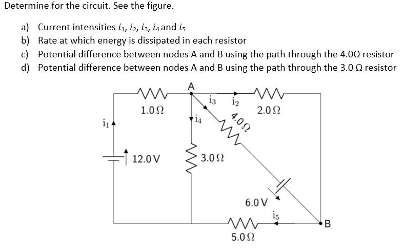
Transcribed Image Text:Determine for the circuit. See the figure.
a) Current intensities 1₁, 12, 13, 14 and is
b) Rate at which energy is dissipated in each resistor
c) Potential difference between nodes A and B using the path through the 4.00 resistor
d) Potential difference between nodes A and B using the path through the 3.0 Q resistor
A
i₁
m
1.0Ω
12.0 V
13
3.0 Ω
1₂
m
2.0 Ω
4.0Ω
6.0 V
ww
5.0 Ω
i5
B
Expert Solution
This question has been solved!
Explore an expertly crafted, step-by-step solution for a thorough understanding of key concepts.

Step by step
Solved in 3 steps with 1 images

Knowledge Booster


Learn more about
Need a deep-dive on the concept behind this application? Look no further. Learn more about this topic, electrical-engineering and related others by exploring similar questions and additional content below.Recommended textbooks for you
Delmar's Standard Textbook Of Electricity
Electrical Engineering
ISBN:
9781337900348
Author:
Stephen L. Herman
Publisher:
Cengage Learning
Delmar's Standard Textbook Of Electricity
Electrical Engineering
ISBN:
9781337900348
Author:
Stephen L. Herman
Publisher:
Cengage Learning