Determine the current flowing through the load resistor, R₁, the current flowing through the output resistor, R₁, and the current flowing through diode D₁ when the output voltage from the opamp is at its maximum value. Diode D, has a maximum power dissipation rating of 30 mW. Is this sufficient for the circuit as shown? Justify your answer. Calculate the proportion of time you expect the output Vo to be high, based on your calculated threshold voltages, when Vi= 8 sin (2π x 5t) V. Express the proportion of time as a percentage and show your working.
Determine the current flowing through the load resistor, R₁, the current flowing through the output resistor, R₁, and the current flowing through diode D₁ when the output voltage from the opamp is at its maximum value. Diode D, has a maximum power dissipation rating of 30 mW. Is this sufficient for the circuit as shown? Justify your answer. Calculate the proportion of time you expect the output Vo to be high, based on your calculated threshold voltages, when Vi= 8 sin (2π x 5t) V. Express the proportion of time as a percentage and show your working.

Introductory Circuit Analysis (13th Edition)
13th Edition
ISBN:9780133923605
Author:Robert L. Boylestad
Publisher:Robert L. Boylestad
Chapter1: Introduction
Section: Chapter Questions
Problem 1P: Visit your local library (at school or home) and describe the extent to which it provides literature...

Related questions

Question
Please provide Handwritten answer of all parts
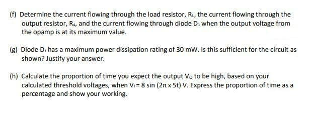
Transcribed Image Text:(f) Determine the current flowing through the load resistor, R₁, the current flowing through the
output resistor, R₁, and the current flowing through diode D₂ when the output voltage from
the opamp is at its maximum value.
(g) Diode D, has a maximum power dissipation rating of 30 mW. Is this sufficient for the circuit as
shown? Justify your answer.
(h) Calculate the proportion of time you expect the output Vo to be high, based on your
calculated threshold voltages, when Vi= 8 sin (2 x 5t) V. Express the proportion of time as a
percentage and show your working.
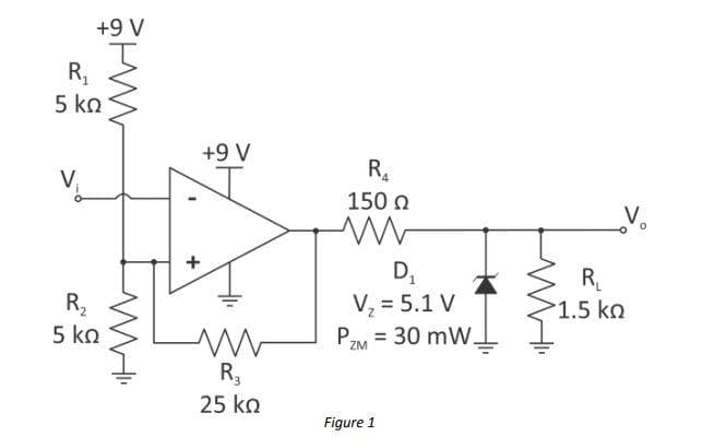
Transcribed Image Text:+9 V
R₁
5 ΚΩ
V
R₂
5 ΚΩ
H
WHI
+
+9 V
www
R₂
25 ko
R₂₁
150 Ω
ww
D₁
V₂ = 5.1 V
PZM = 30 mW.
Figure 1
R₁
>1.5 ΚΩ
Expert Solution
This question has been solved!
Explore an expertly crafted, step-by-step solution for a thorough understanding of key concepts.

Step by step
Solved in 4 steps with 1 images

Knowledge Booster


Learn more about
Need a deep-dive on the concept behind this application? Look no further. Learn more about this topic, electrical-engineering and related others by exploring similar questions and additional content below.Recommended textbooks for you
Introductory Circuit Analysis (13th Edition)
Electrical Engineering
ISBN:
9780133923605
Author:
Robert L. Boylestad
Publisher:
PEARSON

Delmar's Standard Textbook Of Electricity
Electrical Engineering
ISBN:
9781337900348
Author:
Stephen L. Herman
Publisher:
Cengage Learning

Programmable Logic Controllers
Electrical Engineering
ISBN:
9780073373843
Author:
Frank D. Petruzella
Publisher:
McGraw-Hill Education
Introductory Circuit Analysis (13th Edition)
Electrical Engineering
ISBN:
9780133923605
Author:
Robert L. Boylestad
Publisher:
PEARSON
Delmar's Standard Textbook Of Electricity
Electrical Engineering
ISBN:
9781337900348
Author:
Stephen L. Herman
Publisher:
Cengage Learning
Programmable Logic Controllers
Electrical Engineering
ISBN:
9780073373843
Author:
Frank D. Petruzella
Publisher:
McGraw-Hill Education

Fundamentals of Electric Circuits
Electrical Engineering
ISBN:
9780078028229
Author:
Charles K Alexander, Matthew Sadiku
Publisher:
McGraw-Hill Education

Electric Circuits. (11th Edition)
Electrical Engineering
ISBN:
9780134746968
Author:
James W. Nilsson, Susan Riedel
Publisher:
PEARSON

Engineering Electromagnetics
Electrical Engineering
ISBN:
9780078028151
Author:
Hayt, William H. (william Hart), Jr, BUCK, John A.
Publisher:
Mcgraw-hill Education,