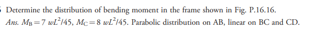
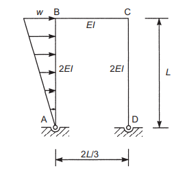
Determine the distribution of bending moment in the frame shown in Fig. P.16.16. Ans. Mg=7 wL²145, Mc=8 WĽ²145. Parabolic distribution on AB, linear on BC and CD.


Q: Determine the reactions and draw the shear and bending moment diagrams for the beams shown in Figs.…
A: Find the fixed end moment for beam AC. FEMAC=wab2L2 =18×20×102302FEMAC =40 k.ft Find…
Q: 1. Solve the frame shown in Fig.1 using moment distribution method. Draw axial force, shear force…
A: Given data Draw axial force, shear force and bending moment diagram.
Q: A.) (Problem 17.17) Determine the member end moments and reactions for the frame shown in figure…
A: NOTE : Since you have asked multiple questions, we will solve the first question for you. If you…
Q: VIII. Determine the member-end moments for the rigid frame with a concentrated couple M=100KN.m…
A: Given M=100Kn-m According to moment distribution mehod M=MAB+MAC+MAD
Q: 30 KN m 4m 4m RA RB RC RO
A:
Q: EXAMPLE Determine the horizontal displacement of point Con the frame shown in Fig. 9-20a. Take E =…
A:
Q: Sample Problem 2 Determine the components of the forces acting on each member of the frame shown.…
A:
Q: Determine the reactions and draw the shear and bending moment diagrams for the beams shown in Figs.…
A: Consider the given beam as follows:
Q: Determine the member end moments and reactions for the frames shown in Figs. by using the…
A: Consider the free body diagram;
Q: Analyze the Vierendeel truss in Figure P11.31 by moment distribution. Draw the shear and moment…
A: For AF qxx=0 qzx=0Nx=-Npi=-25.01 kNVx=Vpi=Mpj-MplengthVx=Vpi=44.39--44.423=29.60…
Q: For the frame shown, the Moment Distribution Method (a) to determine the reactions a b)to draw the…
A: GIVEN- A FRAME REQUIRED- USING moment distribution method, find shear force and bending moment…
Q: 1.Analyze the given frames by solving moment at the supports using moment distribution method,…
A: Solution: Moment Distribution method: Fixed end moment: Span AB: MFAB=-wl220=-12×6220=-21.6…
Q: Determine the member end moments and reactions for the frames shown in Figs. by using the…
A: Consider the flexural rigidity EI of the frame as constant;
Q: Draw the shear and bending moment diagrams and the qualitative deflected shape for the statically…
A: Shear force: Shear force is defined as the algebraic sum of vertical forces acting left or right of…
Q: Determine the member end moments and reactions for the frames shown by using the moment-distribution…
A:
Q: Determine the reactions and draw the shear and bending moment diagrams for the beams shown in Figs.…
A: Draw the free body diagram of the beam Find the value of fixed end moment FEMAC for the segment AC…
Q: 6. Determine the member end moments (BC, CA and CD members) and reactions (B, A, and D) for the…
A: Moment distribution method is used for indeterminate structure where first all joints are considered…
Q: Instructions: Solve the following problems completely using Moment Distribution Method 12 kN/m…
A:
Q: 16.22 Determine the member end moments and reactions for the frames shown in Fig by using the slope-…
A:
Q: Determine the member end moments and reactions for the frames shown by using the slope-deflection…
A:
Q: Determine the reactions and draw the shear and bending moment diagrams for the beams shown in Figs.…
A: Calculate the fixed end moment for the members AB FEMAB=+wL212UDl+wL8PL Substitute the value in…
Q: 9F15 R 9F 15 Ro Mp 3.50 (m) 2.50 (m) 4 (m)
A:
Q: 1.Analyze the given frames by solving moment at the supports using moment distribution method,…
A: Joints are named as below
Q: 50 kN/m D 2 m B 75 kN 1 m A - 4 m -1 m- -21 E = constant
A:
Q: Determine the member end moments and reactions for the frame shown in figure by using following…
A: The portal frame method is based on two assumptions: assumptions: the point of contra flexure lies…
Q: 1. Draw the shear force and bending moment diagrams for the frame shown in the figure using moment…
A: From the given question it is required to draw the shear force and bending moment diagram for the…
Q: 1. Determine the reactions and moments for the beam shown using moment-distribution method. A 18 k 4…
A:
Q: Determine the reactions and draw the shear and bending moment diagrams for the beams shown in Figs.…
A: Fixed end moments MFAB =- 1.5×25212= -78.125 kftMFBA =1.5×25212=78.125 kft MFBC =- 1.5×20212= 50…
Q: 1) Using the Moment Distribution Method calculate the support moments for the beam shown in Figure…
A: In moment distribution method We always find the Fixed end moment by considering the individual beam…
Q: 100kN 150kN 50kN/m E A 6m 3m 3m 3m
A: given - an indeterminate beam to draw - sfd - bmd of beam
Q: 16.1 through 16.5 Determine the reactions and draw the shear and bending moment diagrams for the…
A:
Q: Analyze the frame by moment distribution method. 1. what is the ditribution factor at B for member…
A: 1. what is the ditribution factor at B for member BC? 2. what is the moment(KNm) at C? 3. What is…
Q: R 9F 15 9= 15 H, MA Mp 4 (m) 2 (m) 7 (m)
A:
Q: 16.8 through 16.14 Determine the reactions and draw the shear and bending moment diagrams for the…
A:
Q: Determine the member end moments of the frame shown by using the moment-distribution method. 30 kN/m…
A:
Q: 17.8 through 17.14 Determine the reactions and draw the shear and bending moment diagrams for the…
A:
Q: Determine the member end moments and reactions for the frame shown in Fig. 15.17(a) by the…
A:
Q: 1.Analyze the given frames by solving moment at the supports using moment distribution method,…
A:
Q: Use the unit load method (the principle of virtual work) to determine the rotation, that is, the…
A:
Q: Determine the member end moments and reactions for the frames shown by using the slope-deflection…
A: The compression strength means the material or structure's ability to resist loads that tend to…
Q: RA R R F 46.88 R 34.38 9= 20.88 MA Mp 4 (m) 3 (m) 5 (m)
A:
Q: R 9F 25 R R 25 9 10 H, MA Mp 3.50 (m) 2.50 (m) 4 (m)
A:
Q: Example 8 :Draw the shear, bending moment, and axial force diagrams and the qualitative deflected…
A:
Q: 90 kN 50 kN C B +2m+ 4 m 3 m El = constant FIG. P16.1
A:
Q: Calculate reactions and moments using Moment Distribution Method. Show shear and moment diagram
A:
Q: k) Determine the moments for the beam shown in Fig. by using the slope-deflection method. E= 70 Gpa,…
A:
Q: Using Moment Distribution Method, analyze the frame shown in Fig. (6). Support D moves 3 cm…
A: Using Moment Distribution Method calculation of End Moments ####
Q: 100kN/m C 21 E 21 2m +400kN- 2m B 6m 6m E = 200GPA Figure 2
A:
Q: 25 kN/m D |C 3 m + 75 kN B В El = constant E = 200 GPa I = 400(106) mm4 3 m A 9 m FIG. P17.17,…
A:

Step by step
Solved in 5 steps with 1 images

- B. In Fig. below; rod AB rotates about an axis through A and is connected to block D by a flexible and inextensible cable. Determine the linear velocity of block D when 0 = tan! ( 3 /4 ), and the angular velocity of AB is 2.5 rad / sec counterclockwise. Fig.2.B BQ2: For the beam shown below in (fig 2), calculate the location of the centroidal axis ?̅, forthe cross-sectional area of the T-beam, after that find the moment of inertia I?̀ about the ?̀axis.A.) (Problem 17.17) Determine the member end moments and reactions for the frame shown in figure 17.17 by using moment-distribution method. B.) (Problem 17.21) Solve Problem 17.17 for the loading shown in figure 17.17 and a settlement of 50mm at support D.
- a frame loaded as shown is analyzed by moment distribution method. (a) what is the distribution factor at B for member BC? (b)what is the moment KNm at C? (c)what is the vertical reaction KN at A? (d) what is the horizontal reaction KN at C?Question 5a) Analyse the beam below and draw the shear force and bending moment diagrams. Use the conjugate-beam method to determine the slopes at the ends A and D and the deflections at points B and C of the beam shown in Fig. 1Determine the member end moments and reactions for the frames shown by using the slope- deflection method. Note: Use the 100 kN ∙ m acting at joint C for Equilibrium Equation at the joint, not on FEM’s.
- Determine the member end moments for the frame shown in Fig. 16.15(a) by using the moment-distribution method.The 75-kg man in Figure attempts to lift the 40-kg uniform beam off the roller support at B. Determine the tension developed in the cable attached to B and the normal reaction of the man on the beam when this is about to occur. Choices: A. T=256 N, N = 224N B. T = 512 N, N = 256 NCalculate the reactions and moments using Moment Distribution Method. Show the shear and moment diagram.
- Determine the member end moments and reactions for the frames shown in Fig by using the slope-deflection method for the loading shown and a settlement of 7mm at support A.Determine the reactions and draw the shear and bending moment diagrams for the beams shown in Figs. by using the slope-deflection method.determine the member end moments and reactions for the frames shown in this figure by using slope-deflection method.