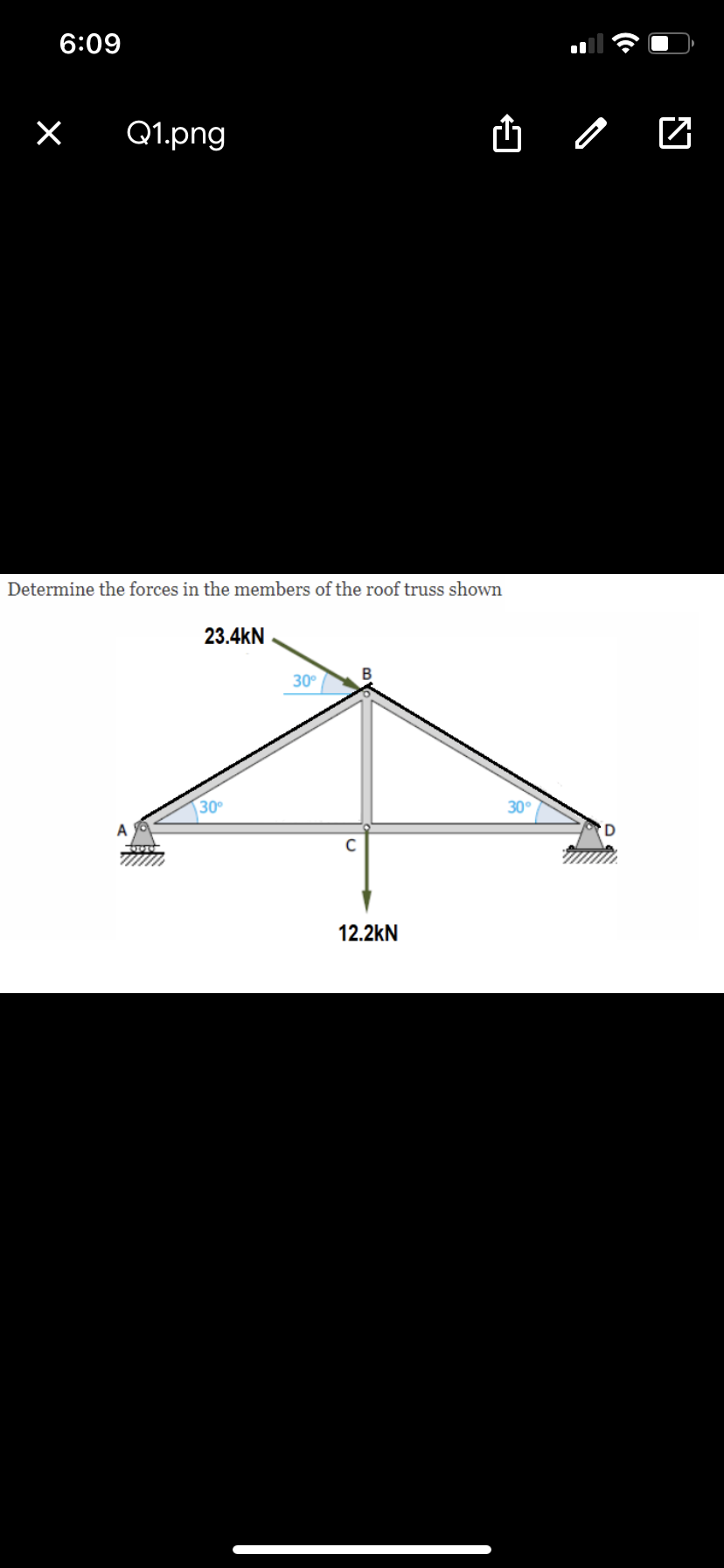
Determine the forces in the members of the roof truss shown


Q: Deter mine all force members O* the truss Shown
A: Solution is given below.
Q: Example 3: Determine the forces in members BC and BG of the loaded truss. 3 kN 3 kN 2m D
A:
Q: rmine the fo
A: take section as shown ∑M=0FEF(4) +[60(cos(20))]…
Q: Dotermine all force of the truss Shown members
A:
Q: Compute the forces in members CD and CG of the loaded truss shown and find the zero- force members.…
A: Given that ,
Q: Determine the force in member BE of the loaded truss. Th
A: Given: TO determine: Force i n member BE
Q: Determine the force in member CD of the loaded truss.
A:
Q: Using the method of joints, determine the force in members AB, AD and DE of the truss shown.
A: Given data as per the question Force applied at point A = 2500 lb Force acting at point B =1500 lb…
Q: Determine the force in each member of the truss shown. State whether each member is in tension or…
A:
Q: Using the method of sections, determine the force in members BC and BG of the roof truss shown.
A:
Q: Determine the force in members GE, GC, and BC of the truss. Indicate whether
A: Given structure:
Q: For the truss shown, determine the forces in members BD and BF and indicate if tension or…
A:
Q: Determine the forces in members DE, DI, and Jl of the arched roof truss shown below.
A: From the symmetry of the truss, the vertical reaction forces can be calculated as, Consider the…
Q: The roof truss is shown below, kindly compute the forces on members GJ, JC, and CD. State whether…
A: Given: The force at each joint of truss is point load.
Q: Determine the forces in each member of the truss shown by the method of joints.
A:
Q: Calculate the force in members AD, BD and BE of the trusses shown. State whether each member is in…
A: Given data: Truss member with given loadings as shown in the figure. To determine: Magnitude of…
Q: Determine the force in members BD and DE of the truss shown.
A:
Q: Determine the forces in members EH and El of the
A:
Q: Problem: Determine the force in members BE, CE, DE, and AB of the truss.
A: Support Reactions : Taking Moments about A, MA = 0 RG ×3 − 4×2 − 5×4 − 6×8 = 0 RG = 17.33 kN ∑Fy = 0…
Q: Use method of section, determine the force in member BE of the loaded truss.
A:
Q: Determine the force in each member of the loaded truss using the method of joints.
A:
Q: Determine the force in members FH, GH, and Gl of the roof truss shown.
A:
Q: Determine the reaction in Kn at support for the three hinged arch shown.
A:
Q: Using the Method of Joints, determine the force in each member of the truss loaded as shown assuming…
A: to find force in member of truss
Q: Determine the forces in members CH, AH, and CD of the loaded truss. Forces are positive if in…
A: Its a symmetrical loaded truss So RA = RG Now taking ∆Fy=0 RA + RG - 1.3- 4.3 - 4.3 - 4.3 - 1.3 = 0…
Q: A floor truss is loaded as shown. Determine the force in members CF, EF, and EG.
A:
Q: Determine the force in each member of the Pratt bridge truss shown. State whether each member is in…
A: The angle from the free body diagram θ=tan-143=53.13°
Q: A fink roof truss is loaded as shown. Determine the force in members BD,CD,CE
A:
Q: A pitched flat roof truss is loaded as shown. Determine the force in members EG, GH, and HJ.
A:
Q: Q1: Determine the force in member CD and DF of truss shown
A:
Q: Determine the force in each member of the Fink truss shown. State whether each member is in tension…
A:
Q: Determine the force in members CE, DE and DF of the truss shown using method of sections.
A: Given: To determine: Force in members CE, DE and DF
Q: Compute the force in member GI and DE of the truss loaded as shown.
A: Determine the zero force members in the truss by using the equilibrium conditions:
Q: Using the method of sections, determine the force in members BD and CD the roof truss shown.
A:
Q: Determine the forces acting in members СВ, CA, CD, DB, DA, and BA of the space truss loaded as…
A: The coordinates of A = (0, 0, 0) Coordinates of B = (4, 0, 0) Coordinates of C = (0, 8, 0)…
Q: In the truss system shown, calculate (a) the reations at support A and I, (b) The forces in each…
A: Only normal reactions will be obtained on these two supports At I there will be two X and Y…
Q: Determine the force in member CD of the truss shown.
A: Given data Given truss system
Q: Determine the force in the members DE, NE and LP of the French truss shown
A: The free-body diagram of the truss is given below,
Q: Determine the forces in members BE and CE of the loaded truss. The forces are positive if in…
A: Answer: BE = 4.2099 kN CE = 5.3001 kN After checking my solution multiple times I am getting the…
Q: For the trusses shown, determine the forces in the member 1, 2 and 3.
A: A truss is an assembly of members organized into triangles. They are generally used in bridges,…
Q: Determine the force acting in members AB, BD and BE of the truss shown
A:
Q: Determine the forces in members BC and BG of the loaded truss.
A: Given structure:
Q: Determine the force in member CD (in kN, round-off to 2 decimal places, include "-" if in…
A: Due to the symmetry the reaction at both the support must be equal. Thus,
Q: Calculate the force in members AD, BD, and CD of the trusses shown. State whether each member is in…
A: Draw the free-body diagram of the given truss. Calculate the angles as shown in the above…
Need answer for this


Trending now
This is a popular solution!

Step by step
Solved in 6 steps with 11 images

- Solve Prob. 10.54 assuming that A and B are connected by a spring of stiffness k = 0.3 W/b and free length b.To determine the reaction forces at supports on a horizontal beam by using the equations of equilibrium for a static application. As shown, beam ABC is supported by the roller at A and pin at C. The geometry of the beam is given by a=2.0a=2.0 ftft, b=7.0b=7.0 ftft, and c=12.0c=12.0 ftft. The applied forces are F1=1.50F1=1.50 kipkip and F2=2.00F2=2.00 kipkip. Force F1F1 is applied at an angle θ=60∘θ=60∘ with the horizontal. Neglect the weight of the beam.(Figure 1)Three bars, two made of aluminum and one made of steel, support a rigid block. An object of weight W is dropped vertically from a distance h above the rigid block. Both steel and aluminum bars have cross-sectional area of 50 mm2 and length of 0.5 m. The elastic moduli for the aluminum and steel are 76 GPa and 184 GPa, respectively. a) If W=1000N and h=0.1m, determine whether the three bars are still safe to perform. b) If h=0.2m, determine the maximum weight that can be dropped without causing failure to the bars
- 2-D PROBLEM: A spherical tank with a radius of 3.41m that has a mass of 28928.644kg was supported in the system shown. Assuming friction and the bar weight is negligible, determine the following: β: 21.774° θ: 46.452° 1. The reaction @ point D. 2. Tension @cable BE 3. The x and y-component of the reaction @ A 4. The reaction @ AA mass M is under tension from wires CD and DE. If CD is 25º from the horizontal while DE is 30º determine the safe value of mass m if the cross sectional areas of the two wires are 80 and 100mm^2 respectively. Maximum allowable stress for wire CD is 30 MPa and wired DE is 40MPa.Three cylinders are piled in a rectangular ditch as shown, neglecting friction. Wa=15lb, Wb=40lb and Wc=20lb. Determine reaction between cylinder A and the floor, reaction between cylinder A and wall, reaction between cylinder A and cylinder B, reaction between cylinder B and cylinder C, reaction between cylinder B and the wall, and reaction between cylinder C and the wall.
- A.The bar of negligible weight is supported by two springs, each having a stiffness k = 98 N/m. If the springs are originally unstretched, and the force is vertical as shown, determine the angle the bar makes with the horizontal, when the 31-N force is applied to the bar. B.Determine the stiffness k of each spring so that the 32-N force causes the bar to tip = 13.6° when the force is applied. Originally the bar is horizontal and the springs are unstretched. Neglect the weight of the bar.The truss shown is subjected to forces P = 68 kN, the length L divided equally, and H = 0.6 m. If the resistance of bar 1 is 151 kN; Determine the maximum length (in meters) of the reinforcement so that the resistance of said bar is not exceeded.The frame shown is composed of members ABCDEF (collar at F), GFHIJ (collar at G), DKI, CLMG, ME, KH and pulley A. Determine the forces experienced by ❤ members ME and KH. The horizontal forces acting in H and I with respect to member GFHIJ are equal in magnitude but opposite in direction. The pulley is frictionless and has a diameter of 1 meter. P = 135 kN d = 11 m j = 4 m
- Springs OA and OB are originally unstretched in a vertical position. Find the horizontal force, F, when the springs are held in the position as shown, given: k = 550 lb/ft, L1 = 0.6 ft, L2 = 1.3 ftApplication of Equilibrium Solve for the value of unknown variables Given : P1 = 6.85 KN P2 = 4.65 KN W1 = 6.15 KN/m Unknowns : RAy , RAx ,RBy , MA What is the value of internal shear 2.50m to the right of support AThe structure shown is composed of an AGJ truss and a KLMO truss connected by the AL link. If it is known that P = 2 kN; R = 5kN; a = 1.5 m and b = 2m, determine:to. The value of the force Q, necessary to keep the system in equilibrium.b. The axial loads of the reinforcement elements. (need free body diagrams)