Determine the internal forces (V, F and M) in member BCD at K. Draw free body diagrams for portion BK and KD. -3.6 m 1200 N 3600 N 2400 N 1.2 m B K CD 2.7 m 2400 N 1800 N 1800 N a B D K 1200 N 2.7 m 1.5 m 3600 N E F E 1800 N G00 N 4.8 m-
Determine the internal forces (V, F and M) in member BCD at K. Draw free body diagrams for portion BK and KD. -3.6 m 1200 N 3600 N 2400 N 1.2 m B K CD 2.7 m 2400 N 1800 N 1800 N a B D K 1200 N 2.7 m 1.5 m 3600 N E F E 1800 N G00 N 4.8 m-

International Edition---engineering Mechanics: Statics, 4th Edition
4th Edition
ISBN:9781305501607
Author:Andrew Pytel And Jaan Kiusalaas
Publisher:Andrew Pytel And Jaan Kiusalaas
Chapter4: Coplanar Equilibrium Analysis
Section: Chapter Questions
Problem 4.163P: Determine the forces in members GI, PH, and GH. Figure P4.162, P4.163

Related questions

Question
3
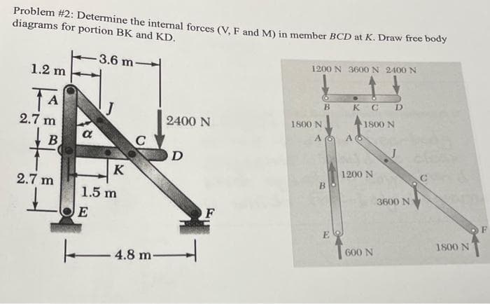
Transcribed Image Text:Problem #2: Determine the internal forçes (V. F and M) in member BCD at K. Draw free body
diagrams for portion BK and KD.
3.6 m
1200 N 3600 N 2400 N
1.2 m
A
B.
K C D
2.7 m
2400 N
1800 N
1800 N
a
C
O D
B
K
1200 N
2.7 m
В
1.5 m
3600 N
O F
E
1800 N
600 N
- 4.8 m-
Expert Solution
This question has been solved!
Explore an expertly crafted, step-by-step solution for a thorough understanding of key concepts.

This is a popular solution!

Trending now
This is a popular solution!

Step by step
Solved in 2 steps with 2 images

Knowledge Booster


Learn more about
Need a deep-dive on the concept behind this application? Look no further. Learn more about this topic, mechanical-engineering and related others by exploring similar questions and additional content below.Recommended textbooks for you
International Edition---engineering Mechanics: St…
Mechanical Engineering
ISBN:
9781305501607
Author:
Andrew Pytel And Jaan Kiusalaas
Publisher:
CENGAGE L
International Edition---engineering Mechanics: St…
Mechanical Engineering
ISBN:
9781305501607
Author:
Andrew Pytel And Jaan Kiusalaas
Publisher:
CENGAGE L