Determine the internal normal force, shear force, and bending moment at point


Q: Determine the internal normal force and shear force, and the bending moment in the beam at points C,…
A:
Q: Determine the normal force, shear force and bending moment at C of the beam.
A: Take origin at B : Shear force equation: Vx=-12x3×1200x Vx=-200x2 NBending moment equation:…
Q: Determine the shear force and moment at point C and D. 500 lb 200 Ib 300 lb 6 ft- 6 ft- 12 ft
A:
Q: 1) The simply supported beam ABCD carries a uniformly distributed load. Derive the shear force and…
A:
Q: Draw the shear and moment diagram, and the elastic curve of the loaded frame shown.
A:
Q: Determine the internal normal force, shear force, and moment at point C.
A: This problem is based on calculation of internal forces and moments with help of the equilibrium…
Q: a.) Determine the moment at arbitrary position x = 1.5m by Method of Section. b.) Draw the complete…
A: Given Data:X=1.5mUDL on span AB=20kN/mConcentrated load at C =40kNUVL on span DE=30kN/mTotal span AE…
Q: Find: At point D: Normal, Shear, and Moment At point E: Normal, Shear, and Moment
A: To Determine At point D: Normal, Shear, and Moment At point E: Normal, Shear, and Moment
Q: find the shear forces and maximum bending moment
A:
Q: Determine the internal normal force, shear force, and moment acting at points B and C on the curved…
A:
Q: Determine the shear and moment equations.
A:
Q: 3. Determine the internal normal force, shear force, and bending moment at point B.
A: Consider section as shown :
Q: Draw shear and moment diagram. Determine maximum shear and maximum moment
A: Calculation of reactionsRA+RC=4.5×12RA+RC=54 eq 1
Q: Draw shear and moment diagram and determine the maximum shear and maximum moment. Use 3 decimal…
A: Given overhanging beam with loading conditions and asked to Draw shear and moment diagram and…
Q: PROBLEM 10 From the beam shown, determine the maximum shear force and maximum bending moment.
A: To determine the maximum shear and bending moment we have to draw a shear force diagram. The point…
Q: Draw the LOAD (w) and the BENDING MOMENT (M) diagrams that correspond to the given shear force…
A: The Joints are named as below
Q: Determine the internal bending moment acting at point C in the beam.
A: Consider FBD for above figure ; 1. Take moment at A ; ∑MA = 0 3 Fb Sin (45) = 30 * 3 Fb = 42.43 KN…
Q: Determine the internal normal force, sheer force, and moment at point C
A: Consider the figure,
Q: The distributed loading w = w0 sin θ, measured per unit length, acts on the curved rod. Determine…
A: First, we draw the free body diagram:-
Q: Determine the internal normal force, shear force, and bending moment in the beam at points C and D.…
A:
Q: Determine the internal normal force (N), shear force (V), and the bending moment (M) at point C. B 3…
A:
Q: Draw the shear and moment diagram using the function of x Locate the maximum moment and its lengtH
A: Given simply supported beam with Trapezoidal loading. It is asked to find shear and bending moment…
Q: determine the normal force, shear force, and moment at point c
A:
Q: -1.5 m→| C В 'A 3 m
A:
Q: Determine the internal normal force, shear force, and the moment at points C and D.
A: Figure is as shown
Q: Determine the internal normal force, shear force, and moment at points D and F in the beam
A:
Q: Find the internal shear force, normal force, and bending moment at point C (3' to the right of…
A:
Q: Determine the internal normal force, shear force, and bending moment in the beam at points B and C.…
A: Given :
Q: Determine the maximum shear (v) and moment(m) of the beam. And sketch the shear force and bending…
A:
Q: -4 m -4 m B 3m
A:
Q: Determine the shear and moment equations in the beam.
A: Take origin as B :Shear equations:i0<x<L2Vx=12xL2×wo×xVx=wox2LMoment…
Q: Draw the shear and moment diagram. Determine the maximum shear and moment.
A: Find reactions:∑ Fy=0RA-75-256=0RA=225KN∑ M=0MA=-756-25612+62MA=2700KN-mShear equations:Vx=225…
Q: Determine the internal normal force, shear force, and bending moment acting at point C in the beam
A:
Q: 400 N/m 200 N/m; A В 3 m- -3 m-
A:
Q: Determine the internal normal force, shear force, and moment in the beam at points C and D. Point D…
A: Consider the summation of forces in the horizontal direction. Ax=0 Consider the equilibrium moment…
Q: Determine the shear force and bending moment of the diagram
A:
Q: Determine the internal normal force, shear force, and bending moment acting at point C in the beam.
A: Data given: Asked: Determine the internal normal force, shear force and bending moment act at…
Q: Draw the shear force, bending moment diagram and mark the salient values. 芒
A: The shear force is the all the force in the beam which is perpendicular to the beam. The bending…
Q: Q3. Determine the internal normal force, shear force and moment at point C of the beam. Draw the…
A: Solution “Since you have posted a question with two sub-parts, we will solve first sub-parts for…
Q: Determine the internal normal force, shear force, and the moment at points C and D.
A:
Q: Draw the shear and moment diagram, determine the maximum value.
A: ∑MB=0-P×L2 + 2P×L2 - RD×L + P×L+L2=0RD=2P∑V=0RB+RD=P+2P+PRB+2P=P+2P+PRB=2PShear force at E=PShear…
Q: : Determine the internal shear force and moment acting at point C in the beam.
A: Find reaction at A:∑ MB=0RA12-12466+63=0RA=8k
Q: F2-3. Determine the magnitude of the resultant force and its direction measured counterclockwise…
A: Given that:
Q: Determine the internal axial force, shear force and bending moment at point C. calculate the…
A: From equalibrium,∑Fy = 0 ⇒ RA + RB = 10 + 1.8 + (8×0.8×sin30o) RA + RB = 15…
Q: Determine the internal normal force, shear force, and moment at points D and F in the beam.
A:
Q: Determine the internal normal force, shear force, and moment at point C.
A: Consider the free body diagram of the beam shown below. Consider the equilibrium moment about point…
Q: 18. The V- and M-equations give the shear and bending moment at every cross section of the beam *
A: Answer:- Shear force:- Shear force at any section is the internal force applied at the section to…
Q: Draw the shear and bending moment diag
A:
Q: 3. Determine the magnitude of the internal normal force, shear force, and the bending moment at…
A:
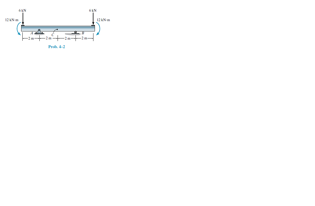
Determine the internal normal force, shear force, and
bending moment at point C.

Step by step
Solved in 2 steps with 1 images

- A flooring system consists of parallel I-beam sections spaced at 3 m on centers with simple spans of 6m. The beam supports a 200mm thick slab that laterally supports the top of the beams. The flooring system is designed for a superimposed load of 1750 N/m^2 The properties of the I-beam sections are: d= 352mm, tw= 7mm bf=170 mm, tf= 10mm Ix= 0.00012m^4, W= 44.85 kg/m Fy- 248 MPa,E= 200,000 GPa 1. Calculate the plastic section of the steel section in mm^3 2. Calculate the nominal strength (kN.m) of an individual beam if it is laterally supported by the concrete slab. 3. Calculate the unfactored service dead load on an individual beam in kN/m 4. Calculate the maximum service live load (kPa) the beam can sustain under LRFD provisions using φb= 0.9 5. Calculate the maximum live load (kPa) the beam can sustain under ASD provisions using Ωb=1.67P12.6 use muller-Breslau principle for this handwritten onlyA W610 x 82 beam of A 36 steel has end reaction of 309 kN and is supported on a plate with a length of bearing of 154 mm. Fy = 248 MPa. Properties: d = 599 mm tw = 11 mm tf = 12.8 mm K = 33.88 Determine the end reaction due to web crippling.
- Design a purlin for a roof truss having the following data:Span of the truss = 6.0mSpacing of truss = 3m c/c.Inclination of roof = 30oSpacing of Purlin = 2m c/cWind pressure = 1.5 kN/m2Roof coverage= A.C Sheeting weighing 200 N/m2Provide a channel section Purlin.Simply Supported Beam ABCDE below carries multiple loads as shown. A built-upsection made from a T-Section and a Channel (C-Section) fastened together by 16mm∅ bolts,equally spaced from the center of the section, with shearing capacity τ=100 MPa, for bearing σb= 220 MPa for rivets in single shear and σb = 280 MPa for rivets in double shear. E=200GPa forall materials. Determine the moment of inertia of the section in x10^6 mm^4Prblm 4c,
- At-beam has a width of flange equal to 700mm and a thickness of 100mm. It has an effective depth of 450mm and the width of the web section is 350mm. It is reinforced at the bottom with a steel area of 2925sq.mm. fc'=17.24MPa, fy=413.7MPa. The ultimate moment capacity of the beam is_kN.mA. 424kN.mB. 444kN.mC. 404kN.mD. 464kN.mA W section steel purlin span 6.7 m between roof trusses on centers. The roof is assumed to support a dead load of 880 N/m2 of roof surface including self-weight and a live load of 816 N/m2 of horizontal roof surface projection. The slope of the roof truss is 1 vertical to 2 horizontal and the purlins are spaced 1 m on centers. Use A36 with Fy = 248 MPa. Assume all loads pass through the center of gravity of the section. Sag rods are to be placed at the middle thirds between trusses. Determine the ratio of the actual to the allowable bending stress. DO NOT ROUND-OFF DURING THE COURSE OF SOLVING. ANSWER IN FOUR DECIMAL PLACES. Properties of W Section A = 2,887 mm2 d = 192.5 mm bf = 100.7 mm tf = 10.82 mm Sx = 174,900 mm3 Sy = 36,133 mm3 tw = 6.1 mm Use the following allowable stresses (NSCP 2001): For bending about strong axis, Fbx=0.66 Fy For bending about weak axis, Fby=0.75Fy(2) sz The bar ABCD is fixed at A by a pin and supported by two wires as shown in fig. the bar is subjected to aload of 75 kN at D. the relation between the movement of point N BtoDis TSN 36B =2 8D 26B =3 6D 8B =4 6D None of all these 26B = 8D O OOO0O0
- A steel rod is bent to form a mounting bracket. For each of the mounting brackets and loading shown, determine the reactions at A and B. Take L = 230mm, F1 = 6ON, F2 = 130 N, M = 14 N.m *The cantilever is statically indeterminate since there are 4 unknowns VA HA MA and VB to solve with only the 3 Rules becomes possible only if at least one action is given. Say for example we are given that MA = 71.65 kNm (hogging). Determine the 3 unknown reactions and on the diagram overleaf, draw the SFD and BMDsA 290 kg/m light crane rail sits on and is securely fastened to a W400mmx67kg/m crane girder.The girder is simply supported on a span of 9m.Assume full transfer of lateral load to the top flange of the girder. Crane wheel loads: Vertical load at the centroid (V)=80kN Horizontal load at the top flange (H)=8kN Properties: A=8580 mm^2 d=400 mm bf=179 mm tf=14 mm Ix=244 x 10^6 mm^4 Iy=14 x 10^6 mm^4 tw=8.5 mm a.what is the maximum bending stress fbx(MPa) in the girder? b.determine the maximum bending stress fby(MPa) in the girder c.Using the interaction formula fbx/Fbx + fby/Fby