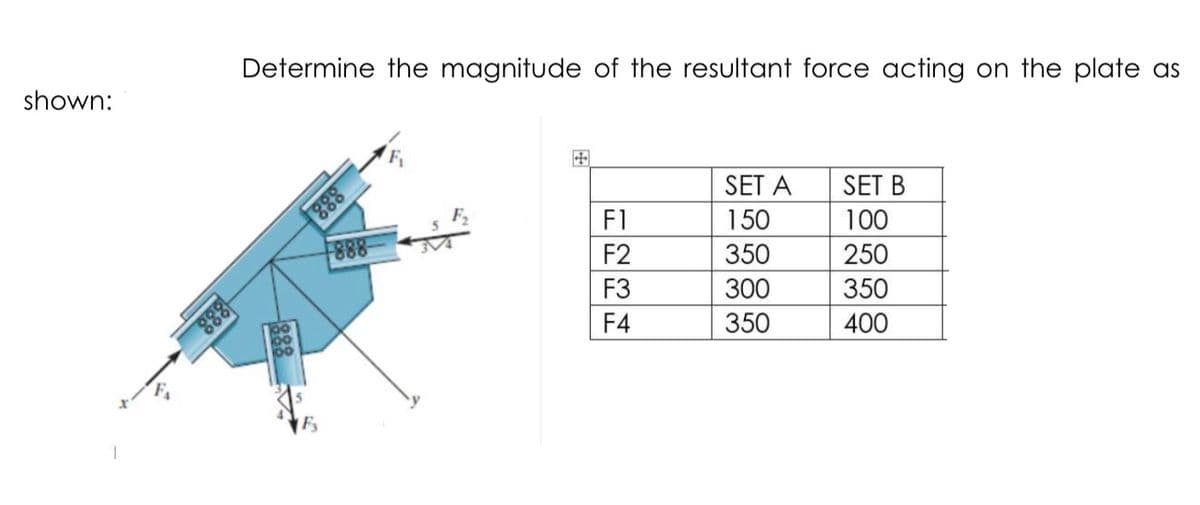
Determine the magnitude of the resultant force acting on the plate as shown: 田 SET A SET B 888 F1 150 100 F2 350 250 888 350 F3 300 F4 350 400 888


Q: 3k 30lbs 40° 40°
A:
Q: Determine the deformation of the steel rod (inches) in the figure shown under the given loads Given:…
A:
Q: Problem 1. Determine the resultant of the four forces acting on the eye bolt as shown. F2= 160 N 20°…
A: Determine the resultant of the four forces acting on the eye bolt as shown.
Q: 4. An assembly of three rods is shown in Fig. 4. The rods each have the same 25-mm diameter and…
A: free body diagram at joint A
Q: Example Determine the x and y components of each force acting on the gusset plate of a bridge truss.…
A: Given: F1 = 8 kN F2 = 6 kN F3 = 4 kN F4 = 6 kN
Q: 14. The magnitude of the three forces acting on the plate are T, = 100 kN, T2 = 80 kN, and T3 = 50…
A: Given that: T1=100 KN, T2=80 KN & T3=50 KN
Q: 1. A steel bar ABC of 400 mm length and 20 mm diameter is subjected to a point loads as shown in…
A: Given data : Modulus of elasticity (E)=200 GPaLength of AB (LAB)=200 mmLength of BC (LBC)=200…
Q: Determine the stress of the tension steel. 200 }60 20mm 450 32mm 60 111.43 11.143 12.38 100.29
A: Given Cross section details Calculate location of neutral axis because there is no information…
Q: Practice Problem 4.4.4: The homogeneous 200-lb sign is suspended from three wires. Find the tension…
A: Free body diagram of given structure:-
Q: Q1: determine the magnitude and location of the resultant force of the force system shown: 40 lb 30…
A:
Q: The man shown pulls on the cord with a force of 70 lb. Represent this force acting on the support A…
A:
Q: Give all numerical values at all change of loading positions and at all points of zero shear. Use…
A: Analytical tools such as shear force and bending moment diagrams are used in conjunction with…
Q: 8. Determine the magnitude and coordinate angles of the resultant force acting at A. daB dac R in…
A:
Q: Q.11. Two forces are applied to the construction bracket as shown. Determine the angle which makes…
A:
Q: y 150 mm 150 mm B 400 mm 600 mm A
A:
Q: A force of 200 lbs is exerted on a block at an angle of 28° with respect to the horizontal. The…
A:
Q: The system shown is in static equilibrium and motionless. All joints are ideal. • The origin of the…
A:
Q: Assignment Determine the magnitude of the component force in Fig 2 13 a and magnitude of the…
A: To find force F and resultant FR
Q: To points A, B, C, and D respectively on an infinite-length plate Parallel forces FA, FB, FC and FD…
A:
Q: PROBLEM 1: Determine the resultant (magnitude and direction) of the three forces acting on the…
A:
Q: Determine the stress of the tension steel. 200 60 20mm 450 32mm 60 111.43 11.143 12.38 100.29
A:
Q: Determine the resultant internal loadings (n,M & V) at point C in the beam. Assume the support…
A: Consider the free body diagram Consider the moment about C ; C+∑MC=0-5×1.5+Dy+3=0Dy=2.5 kN∑Fn=0Cx=0…
Q: Replace the loading acting on the beam by a single resultant force. Specify where the force acts,…
A: To find Single resultant force, Fr and the location where it is acting, d
Q: Resolve each force acting on the gusset plate into its x and y components, and express each force as…
A: Given :
Q: Situation 4. Three forces are acting at the given plate 7. Replace the loading by an equivalent…
A:
Q: Replace the five forces acting on the plate by a wrench. Suppose that F1 = 700 N and F2 = 550 N .…
A:
Q: Example 1 Determine the resultant of the four forces and one couple which act on the plate shown. 2…
A:
Q: 2. Given the system of forces shown below, Determine the following (a) Moment of the 361-lb force…
A:
Q: While cutting a piece of paper, a person exerts the two indicated forces on a paper cutter. Reduce…
A: Solution; Given that; Dimension of paper cutter=30"×30"
Q: What is the total elongation of steel bar having a diameter of 2 in. hanging over with a length of…
A:
Q: The pipe assembly is subjected to a force of 600 N at B. 150 mm 150 mm Part A 400 mm B 60° 30° 600 N…
A:
Q: Q) Four forces act on an eye bolt as shown in figure below. Determine the resultant and direction of…
A: Given:- Four forces are acting on an eye bolt The magnitude of force F1 = 30 N The magnitude of…
Q: Determine the resultant of the four forces and one couple which act on the plate shown. 2 m 5 m 60 N…
A: Given:- Four forces and a couple are acting on the plate The magnitude of the forces are = 60 N, 50…
Q: F, kN Fa kN F, kN/m B D 4, kN-m F R1 2 m 1m 2 m 2 m 2 m R2 3 m F1 =45; F2 = 36; F3 = 135; F4 = 60
A:
Q: Example Determine the x and y components of each force acting on the gusset plate of a bridge truss.…
A:
Q: A steel tape having a cross-sectional area of 0.055 cm^2and a modulus of elasticity of 2.1x 10^6…
A:
Q: The pipe assembly is subjected to a force of 600 N at B. 150 mm 150 mm 400 mm B 30 600 N 500 mm Q…
A: Given values: Force at B, FB = 600 N
Q: Enicognito Given the 180 mm x 360 mm rectangular beam as shown in the figure. 100 kN/m 20 kN-m 50…
A:
Q: Determine the magnitude of the resultant force acting on the plate as shown: SET A SET B 888 100 F1…
A: To Determine The magnitude of the resultant force acting on the plate.
Q: 国 SET A SET B SET C 888 F1 150 100 200 F2 350 250 350 888 F3 300 350 250 888 F4 350 400 400 888
A:
Q: 4. The resultant of the three concurrent forces acting on the eyebolt is the force R = 600j lb.…
A: Given Data: The force F1=800 lb. The angle of inclination of force F1 is θ1 The force F2=400 lb. The…
Q: 300 lb 30° 1' 224 lb 361 lb
A:
Q: Example: Determine the resultant of the three tension forces acting on the eye bolt. 30 4 kN 20 KN 8…
A: Given data Find resultant of the three tension force
Q: Determine the axial force (kN) in each member of the assembly shown below, Member Cross-Sectional…
A:
Q: Two forces are applied to the construction bracket as shown. Determine the angle which makes the…
A: Answer We are given F1 = 700 lb F2 = 460 lb α = 56 degree As the given force system is concurrent…
Q: From the given figure of space force on the right, determine the: 6. EF along x-axis 17 4-m 180 lbs…
A: Find resultant of three forces,R?
Q: 4. Locate the magnitude and position of the resultant of the loads acting on the fink truss. 400 Ib…
A:
Q: Determine the x and y components of each of the forces shown. a. y F = 1200 lb
A: The given data is: F=1200 lb θ=60°
set b

Step by step
Solved in 3 steps with 3 images


- The class is called ARC2501 architectural structues at St. Petersburg College If unable to answer please direct me to someone who can. For beam 2 find reactions R1and R2 Show sheaer magnitude at each support show magnitude and location of maximum shar (Vmax) show magnitude and location of maximum Moment (Mmax)Sketch the cross-sectional picture of a W8x67 sitting on top of a W16x26 (the vertical centerlines are colinear). NOTE: The webs are vertical. The magnitude of the Area Moment of Inertia about the horizontal centroidal axis of the built-up member is _____in4.A 0.65kg, 50m tape was standardized and supported throughout its whole length and found to be 0.00205m longer at an observed temperature of 31.8°C and a pull of 10KN. This tape was used to measure a 4% prade line which was found to be 662.702m. During measurement, the temperature is 15°C and the tape is suspended under a pull of 20KN. E-200GPa, cross-sectional area of tape is 3mm2 and the coefficient of linear expansion is 0.0000116m/°C. Compute the true horizontal distance.
- A wide flange section is used as beam to support a concrete floor system. The beam is simply supported over a span of 6m. The properties of the section are given as follows:Depth, d = 498mmWeb thickness, tw = 56mmMoment of Inertia about x-axis, Ix = 3417 x 106 mm4Section Modulus about x-axis, Sx = 13730 x 103 mm3Self-weight, wself-weight = 7.32 kN/mAssume the beam is laterally supported over its length with its allowable stress in bending is 0.66Fy and its allowable shear stress is 0.40Fy assuming direct shear stress is used as basis instead of flexural shear stress. The allowable deflection is set at L/360. Use A36 steel with Fy = 250 MPa. (a) Compute for the safe uniform load (w) without exceeding the allowable shear stress. (b) Compute for the safe uniform load (w) without exceeding the allowable bending stress. (c) Compute for the safe uniform load (w) without exceeding the allowable deflection.y=25kN/m P1=24kN P2=7kNfind out F, KN F23 f13 f16
- 30 - A homogeneous, planar plate of constant thickness in the figure the coordinates of the centroid M(Xm,Ym) of the surface area, Find the team (x,y). t= 3 cm and a= 9 cm. Find the coordinate (Ym) of the center of gravity of this planar plate on the y axis.A) 14.18B) 15.05C) 15.62D) 12.25E) 17.5Topic: BEAM BEARING PLATES AND COLUMN BASE PLATES Please solve your Solution in a handwritten Note: It should be handwritten pleaseeee A w24 X55 is used as a beam with a length of 6m. The beam is supported by a bearing plate of 300 mm x 200 mm x 30 mm on the wall having a thickness of 250 mm.Properties: d=598.68mmbf = 177.93 mmtw =10.03mm k=33.34 mmtf = 12.83mmFy = 250 MPaQuestions:1. Determine the design strength for web local yielding.2. Determine the design strength for web crippling.A line was determined to be 354.7654 m when measured with a 50-m steel tape supported throughoutits length under a pull of 4,567 kg at a mean temperature of35.495'C. Tape used is of standardlength at 20.0°C under a pull of 5.435 kg. Cross-sectional area of the tape is 0.0367cm2.Coefficient of thermal expansion is 0.00001160/C. Modulus of elasticity of tape is 2x10⁶ kg/cm2.Determine the corrected length of the line.
- A line is recorded as 472.90m long. It is measured with a 0.65kg tape which is 30.005m long at 20C under a 50N pull supported at both ends. During measurement, the temperature is 5C and the tape is measured on 3% grade. E=200GPa. cross sectional area of tape is 3mm and the coefficient of linear expansion is 0.0000116m/"C. A) how did you assume the value of pull at temperature 5 degrees is 75N ....The given force in the figure passes through from the origin to point A(5,-12,16). Its y-component is please answer within 15 minutessolve accurate do not copy previous posted answers those are incorrect... i will upvote if yougive right answer A traffic light signal pole is subjected to the weight of each traffic signal 45 lbs and the weight of the road lamp 55 lbs . The weight of lateral arms is included in the signal and lamp weights. The people is fixed and the base and is made of round structural steel section HSS 14.000 x 0.25. The details of the pole section may be obtained form the Manual of American society of steel Construction (AISC Steel Manual). Analyze the principle normal stresses and the maximum shear stresses on elements A and B located at the base in the pole as shown in the sketch below.