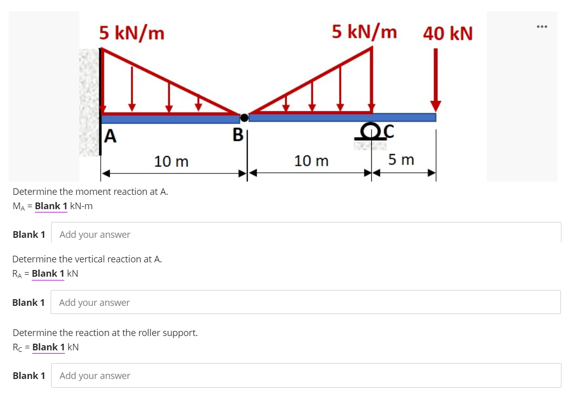
Determine the moment reaction at A. MA = Blank 1 kN-m Blank 1 Add your answer Determine the vertical reaction at A. RA = Blank 1 kN Blank 1 Add your answer Determine the reaction at the roller support. Rc = Blank 1 kN


Q: Q1-B- Draw just the Free Body Diagram of the following figures. 30 kN/m - 3 m - 3 m - 3 m --- 4 kN/m…
A:
Q: Determine the support reactions at A for the beam with built-in ends. 900 N/m -2 m-
A:
Q: Number 1
A: Solution: The reaction at A and B is calculated for the given beam as : The total load on the beam…
Q: 5. Determine external reactions at D and E and all pin forces at A, B and C. Note: Ignore point J in…
A:
Q: The truss is shown. Indicate direction to your final answer. a.) What is the vertical reaction…
A:
Q: For the bracket and loading of Prob. 4.7, determine the smallest distance a if the bracket is not to…
A: When bracket is not to move, the reaction force at A will be zero i.e. the bracket will be in…
Q: The frame as shown in the Figure consist of two members AC and BE. Calculate the following: 1-…
A:
Q: For the truss loaded as shown in Figure 5, make calculations for the reactions at the support and…
A: Use Pythagoras theorem to calculate the distance AE. Calculate the angle θ.
Q: Calculate the internal reactions for the member shown at sections M-M and N-N [1.5 kN 0.6 m, 0.7 m…
A: A pin support will exert both horizontal and vertical components of reaction. The support A is pin…
Q: 20 KN 20 kN -6 m -6 m If the support reaction at B is 48 kN for the shown beam, the load (P) equals.…
A: P1= 20 KNP2=20 KNP3=PsinθRB= 48KN
Q: 4.24 Determine the reactions for the beam shown. The beam has a pinned support at one end and a…
A: Given Data :
Q: Problem 2) From the figure below, determine: 1. the horizontal reaction at A; 2. the vertical…
A:
Q: Question 2 For the truss loaded as shown in Figure 5, make calculations for the reactions at the…
A: From Figure, tanθ=EMAMtanθ=11θ=45o
Q: Calculate the reactions at A and B for the beam shown. 24 kN 24 kN 12 kN/m D E 1,8 m 0.6 m 0.6 m 0.6…
A:
Q: 6-34 A beam is loaded and supported as shown in Fig. The beam has a uniform cross section and a mass…
A: Given mass of beam (m) = 180 kg To determine Reactions at support A
Q: Find the moment reaction at C (Mc), given that W 43 KN. Neglect the weights of the members as well…
A:
Q: a)Determine the moment components of Mx at O to maintain equilibrium? (answer in kN.m)) b)Determine…
A: As per our guidelines we are supposed to solve only 3 subparts if multiple subparts are asked .…
Q: If the beam in the figure below is in equilibrium (A is a pin and B is a roller), determine the…
A:
Q: Calculate the reactions at the support: а. Аy b. Вy -0.8 m 6 kN/m 3 kN/m OB 3 kN/m 6 kN/m 1.6 m 4 m…
A: The Answer is below
Q: 10 KN/m 3 m 3 m
A: Answer: RA = 26.25 kN RB = 18.75 kN For a step-by-step solution have a look through the attached…
Q: A beam ABCDE is simply supported at A and D. It carries the following loading: a distributed load of…
A: Shear force at any section is found by the summation of all the shear force on either left or right…
Q: Find the reaction at A due to the uniform loading and the applied couple. The force reaction is…
A: From equilibrium; ΣFy = 0; RA = -2.5 * 2 RA = 5 kN
Q: The overhanging beam is supported by a pin at A and the two force strut BC as shoen in figure. A)…
A:
Q: 4.1 Calculate the magnitude and direction of the reactions at support A and B using the moment law.…
A: for solution refer below images.
Q: If the beam in the figure below is in equilibrium (A is a pin and B is a roller), determine the…
A: First of all, make a FBD of the diagram as shown below,
Q: The frame as shown in the Figure consist of two members AC and BE. Calculate the following: 1-…
A:
Q: B/ Calculate the reactions at the support in the cantilever beam shown in Fig. below. The beam has a…
A:
Q: 6-33 A beam is loaded and supported as shown in Fig. The beam has a uniform cross section and weighs…
A: Given Data: Force applied on beam is F = 2500 lb. Length of beam is L = 12 ft. The weight of beam…
Q: For the beam shown below: - Draw the free body diagram showing the reactions for each type of…
A:
Q: 600 lb C 18 25 750 lb-ft B 10 900 lb| Dimensions in inches
A:
Q: Find the reactions for the supports on the frame below. P is 24 kN in the y direction, F is 12 kN in…
A: Given:
Q: Use the picture to solve these questions 1-The magnitude of the moment induce by the load about the…
A: The coordinates of the points, The applied force,
Q: Find the reactions at the supports for the 17 kN beam shown below, if the length of the beam is 14m,…
A:
Q: For the beam shown below: - Draw the free body diagram showing the reactions for each type of…
A:
Q: 20 KN 20 KN 20 KN 20 KN/m 20 KN-m
A: To determine the reaction at point B.
Q: Find the reaction at A due to the uniform loading and the applied couple. The force reaction is…
A: The free body diagram of the beam is as follows: Horizontal reaction in the beam as follows: Ah=0…
Q: Current Attempt in Progress Find the reaction at A due to the uniform loading and the applied…
A:
Q: Prob. From the given Figure. 150 KN 90° 180 KN 2m A Im Reg'd (1) Vertical reaction at the hinge (2)…
A:
Q: Determine the magnitude of the moment (in kip-ft) at B of member BC of the frame shown below. Assume…
A:
Q: - Portions AB and CD have flexural rigidity EI, and portion BC has flexural rigidity 3EL Determine…
A:
Q: 6 kN 30° 30° 1.5 m 4 kN A -1.5 m -1.5 m
A:
Q: Find the horizontal and vertical reactions at the pin at B. Note that the support at D is fixed.…
A:
Q: 29 kN/m Hinge 14.5 kN/m 3 m Calculate the reactions at the + Support and he reactions of the hnges 3…
A:
Q: Solve for the reactions (in kN) at the hinge and roller support of the overhanging beam shown below.…
A:
Q: The moment reaction at support O equals to zero
A:
Q: APPROXIMATE ANALYSIS OF INDETERMINATE STRUCTURES S T Solve the reactions at the support and the…
A: Please find the solution below
Q: Determine the reactions at point A and B of the parallel force system shown in the figure to the…
A:
Q: 3 m -3 m *-3 m 3 m B C 4 m H 10 kN 15 kN 5 kN A) Use method of sections to find the forces in CD,…
A:

Step by step
Solved in 3 steps with 3 images

- , Solve the preceding problem using the numerical data: /) = 90mm, h = 280 mm, d = 210 mm, q = 14 kN/m, and L = L2 m..17 A mountain-bike rider going uphill applies torque T = Fd(F = l5lb, d = 4 in.) to the end of the handlebars ABCD by pulling on the handlebar extenders DE. Consider the right half of the handlebar assembly only (assume the bars are fixed at the fork at A). Segments AB and CD are prismatic with lengths L, = 2 in.andL3 = 8.5 in, and with outer diameters and thicknesses d01 = 1.25 in. 101 = 0.125 in. and d03 = O.87in.,i03 = 0.ll5in, respectively as shown. Segment BC’ of length L, = 1.2 in. however. is tapered, and outer diameter and thickness vary linearly between dimensions at B and C. Consider torsion effects only. Assume G = 4000 ksi is constant. Derive an integral expression for the angle of twist of half of the handlebar tube when it is subjected to torque T = Fd acting at the end. Evaluate ‘b1-, for the given numerical1ues.-7 Repeat Problem 2.3-5, but n include the weight of the bar. See Table I-I in Appendix I for the weight density of steel.
- Beam loaded as shown in Fig. below. Determine the Following: Reaction support at point B. a. 56KN (Downward Direction) b. 56KN (Upward Direction) c. 35KN (Downward Direction) d. 35KN (Upward Direction) Reaction support at point D. a. 26 KN (Downward Direction) b. 26 KN (Upward Direction) c. 24KN (Downward Direction) d. 24KN (Upward Direction) Shear force equation of section AB. a. -30KN b. 30KN c. -32KN d. 32KN Shear force equation of section CD. a. -24KN b. 24KN c. -28KN d. 28KN Bending moment equation of section BC. a. 26KN(x)+56KN.m b. 26KN(x)-56KN.m c. -26KN(x)+56KN.m d. None of the above. Maximum bending moment of the beam. a. 47KN.m b. 46KN.m c. 48KN.m d. None of the abovets=600g, TL=18pounds , angle=780degree ,can you please find the solution and free body diagramGiven:a. the force in BD=25KNb. vertical reaction at point C=-10KNc. horizontal reaction at point C=15KNd. resultant of reaction at point C=18.0KNe. allowable tensile (normal) stress in member BD =83.33MPaf. the allowable shear stress in the pin at C =72.7MPaPlease help me solve for:1. What is the required cross-section area and minimum thickness t of member BD?2. What is the required SHEAR cross-section area at point C?3. What is the minimum diameter for the pin at C?(Solve for a value with the combination of mm and N)
- Steel bar in shape, AAB 600 mm and ABc = DACD3D 1200 mm2 are made of two stages. Determine the displacement at end A in (mm). E = 200 GPaA beam is loaded and supported as shown in Fig. P6-39. The beam has a uniform cross section and weighs 40 lb. The pulley at B weighs 50 lb. Determine the reaction at support A and the tension Tin the cable.a) The factors of safety predicted at point H by the maximum shear stress theory of failure (Tresca criterion) i) The second moment of area relative to z-axis, I_z, for the cross-section can be calculated as ( Enter your answer in cm4 ii) The bending stress at Point H can be calculated as (Enter your answer in MPa, Compressive stress is negative and tensile stress is positive) iii) The first moment of area required to calculate shear stress at H can be calculated as (Enter your answer in mm^3) iv) The absolute value of the transverse shear stress at point H can be calculated as (Enter your answer in MPa ) v) Maximum principal stress can be calculated as (Enter your answer in MPa ) vi) Minimum principal stress can be calculated as (Enter your answer in MPa ) vii) The equivalent stress for Maximum-Shear-Stress Theory ( Tresca criterion) (Enter your answer in MPa ) b) The von Mises equivalent stresses at point H can be calculated as: MPa c) The factors of safety at point H…
- The shaft, is driven by pulley B from an electric motor. Another belt drivefrom pulley A is running a compressor. The belt tensions for pulley A are 1500 N and 600 N. The ratioof belt tensions for pulley B is 3.5. The diameter of pulley A is 150 mm and the diameter of pulley B is 480 mm. The allowable tensilestress for the shaft material is 170 MPa and the allowable shear stress is 85 MPa. Taking torsion andbending factors as 1.25 and 1.75 respectively, find the shaft diameter.Also find out the dimensions for a hollow shaft with outside diameter limited to 30 mm. Compare theweights of the two shafts. [Ans. 30 mm ; 24 mm ; 1.82 Given Length CD=350mm Length AB=150mm Length BD=100mm The total length is CD =350Hoop stress is limited to (2.4)MPa and density of flywheel material is (7504) Kg/m3The solid-circular member AC, having a diameter D and a shear modulus of 69 GPa, is subjected to the torques 2T and 3T at points A and B, respectively. If tallow = 35 MPa and (fA/C)allow =2o, determine the maximum permissible value of the torque T. Use the table given below and your student ID to find the values of L1, L2, and D. Student ID L1 (m) L2 (m) D (mm) 1131731 1 0.6 78