Determine the Q-point for the circuit. Find maximum peak value of base current for linear operation. Assume Boc = 200. week 12-2.jpg ... Rc 330 N RB Vcc 20 V 47 kN VR BB 10 V IBQ = Blank 1 uA ICQ = Blank 2 mA %3D VCEQ = Blank 3 V
Determine the Q-point for the circuit. Find maximum peak value of base current for linear operation. Assume Boc = 200. week 12-2.jpg ... Rc 330 N RB Vcc 20 V 47 kN VR BB 10 V IBQ = Blank 1 uA ICQ = Blank 2 mA %3D VCEQ = Blank 3 V

Delmar's Standard Textbook Of Electricity
7th Edition
ISBN:9781337900348
Author:Stephen L. Herman
Publisher:Stephen L. Herman
Chapter30: Dc Motors
Section: Chapter Questions
Problem 6RQ: What is CEMF?

Related questions
Question
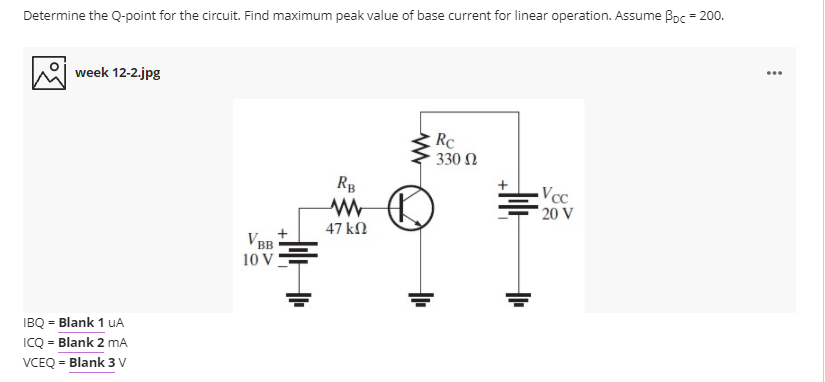
Transcribed Image Text:Determine the Q-point for the circuit. Find maximum peak value of base current for linear operation. Assume Boc = 200.
...
week 12-2.jpg
Rc
330 Ω
RB
Vcc
20 V
47 kN
V BB
10 V
IBQ = Blank 1 uA
ICQ = Blank 2 mA
%3D
VCEQ = Blank 3 V
Expert Solution
This question has been solved!
Explore an expertly crafted, step-by-step solution for a thorough understanding of key concepts.

This is a popular solution!

Trending now
This is a popular solution!

Step by step
Solved in 2 steps with 2 images

Recommended textbooks for you
Delmar's Standard Textbook Of Electricity
Electrical Engineering
ISBN:
9781337900348
Author:
Stephen L. Herman
Publisher:
Cengage Learning
Delmar's Standard Textbook Of Electricity
Electrical Engineering
ISBN:
9781337900348
Author:
Stephen L. Herman
Publisher:
Cengage Learning