Determine the subtransient fault current in per-unit and in kA, as well as the per-unit line-to-ground voltages at the fault bus for a bolted single line-to-ground fault at the fault bus selected in Problem 9.2. Repeat Problem 9.14 for a bolted double line-to-ground fault.
Determine the subtransient fault current in per-unit and in kA, as well as the per-unit line-to-ground voltages at the fault bus for a bolted single line-to-ground fault at the fault bus selected in Problem 9.2. Repeat Problem 9.14 for a bolted double line-to-ground fault.

Power System Analysis and Design (MindTap Course List)
6th Edition
ISBN:9781305632134
Author:J. Duncan Glover, Thomas Overbye, Mulukutla S. Sarma
Publisher:J. Duncan Glover, Thomas Overbye, Mulukutla S. Sarma
Chapter9: Unsymmetrical Faults
Section: Chapter Questions
Problem 9.14P

Related questions

Question
Only need answers for the second question(9.17) at bus 1.
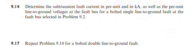
Transcribed Image Text:9.14 Determine the subtransient fault current in per-unit and in kA, as well as the per-unit
line-to-ground voltages at the fault bus for a bolted single line-to-ground fault at the
fault bus selected in Problem 9.2.
9.17
Repeat Problem 9.14 for a bolted double line-to-ground fault.
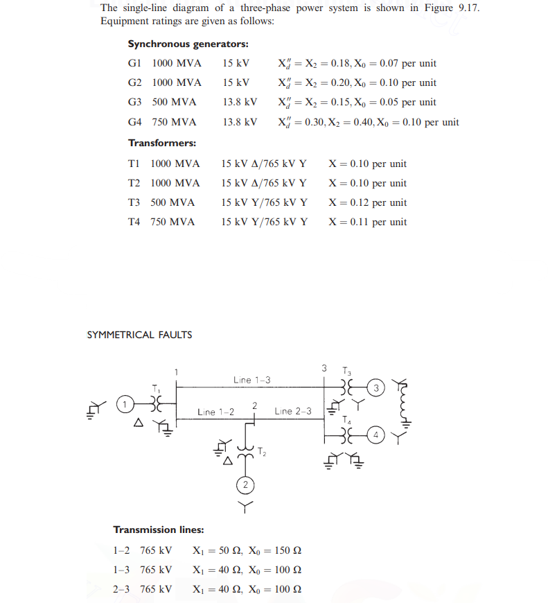
Transcribed Image Text:The single-line diagram of a three-phase power system is shown in Figure 9.17.
Equipment ratings are given as follows:
Synchronous generators:
G1 1000 MVA
15 kV
1000 MVA
G2
G3 500 MVA
15 kV
13.8 kV
13.8 kV
G4 750 MVA
Transformers:
T1 1000 MVA
T2 1000 MVA
T3 500 MVA
T4 750 MVA
SYMMETRICAL FAULTS
Line 1-2
Transmission lines:
1-2 765 kV
1-3 765 kV
2-3 765 kV
15 kV A/765 kV Y
15 kV A/765 kV Y
15 kV Y/765 kV Y
15 kV Y/765 kV Y
₁²
◄
Line 1-3
2
2
X = X₂ = 0.18, Xo = 0.07 per unit
X = X₂ = 0.20, Xo = 0.10 per unit
X = X₂ = 0.15, Xo = 0.05 per unit
X = 0.30, X₂ = 0.40, Xo = 0.10 per unit
T₂
Line 2-3
X₁ = 50 £2, Xo = 150 2
X₁ = 40 92, Xo = 100 2
X₁ = 40 92, Xo = 100 2
X = 0.10 per unit
X = 0.10 per unit
X = 0.12 per unit
X = 0.11 per unit
3 T3
T₁
4
youthy
Expert Solution
This question has been solved!
Explore an expertly crafted, step-by-step solution for a thorough understanding of key concepts.

This is a popular solution!
Step 1: Given
VIEWStep 2: Per unit reactances for generators
VIEWStep 3: Per unit reactances for transformer and tranmission lines
VIEWStep 4: Sequence network
VIEWStep 5: Fault current in per unit
VIEWStep 6: Sub transient fault current in pu and KA
VIEWStep 7: Line to ground voltages at the fault bus
VIEWSolution
VIEW
Trending now
This is a popular solution!

Step by step
Solved in 8 steps with 31 images

Knowledge Booster


Learn more about
Need a deep-dive on the concept behind this application? Look no further. Learn more about this topic, electrical-engineering and related others by exploring similar questions and additional content below.Recommended textbooks for you
Power System Analysis and Design (MindTap Course …
Electrical Engineering
ISBN:
9781305632134
Author:
J. Duncan Glover, Thomas Overbye, Mulukutla S. Sarma
Publisher:
Cengage Learning
Power System Analysis and Design (MindTap Course …
Electrical Engineering
ISBN:
9781305632134
Author:
J. Duncan Glover, Thomas Overbye, Mulukutla S. Sarma
Publisher:
Cengage Learning