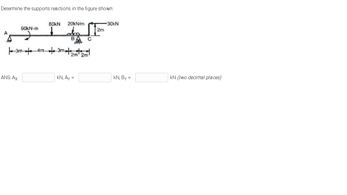
Determine the supports reactions in the figure shown: 80KN 20kN/m -30kN 60KN-m 2m BA C -3m- am-te-3mat 2m' 2m ANS: Ax kN, Ay = kN, By kN (two decimal places)


Q: For the figure shown below, find the reactions at ?supported A and C äbäi 60 20KN Hing. B. 2m 2m 2m…
A: Let reactions at A be HA and VA and that of B be HB and VB. Take (+)ve sign for horizontal forward…
Q: C3/(a) For the figure below take M number of you and find the reactions * ? 3 m 3 m 3 m E C 12 M 13…
A:
Q: 2. The bracket BCD is hinged at C and attached to a control cable at B. For the loading shown in…
A: To find : determine the tension in the cable and the reaction at C.
Q: 20 kN/m 6m Determine reactions in A and tension in cable as shown in figure? 300 kN 30 kN/m B 8 m…
A:
Q: etermine the reactions RA and Rg of the beam loaded as shown in the figure. 600 lb 200 lb 5'- 4' A…
A:
Q: Calculate the internal reactions for the member along section M-M shown in the Figure. 6 lb/ft 9 ft…
A: Since the end A is knife edge supported thus there will be two support reactions i.e. one in…
Q: C3/(a) For the figure below take M number of you and find the reactions ? * 3m - 3m 3 m E 12 36 13 3…
A:
Q: H.W. 3 / Find the reactions of the simply supported beam shown in Figure below 200 lb 400 lb-ft A |B…
A: Given RAy=200 lb
Q: Q2: Bar of cross section 8 mm x 8 mm & 800 mm long is fixed at both ends. Determine the end…
A:
Q: 1) Find the support reactions at static equilibrium for the loaded beam shown below in Fig4.1 6'…
A:
Q: Q: The bar AB is pinned at A and rest on roller at B. The bar AB is loaded as shown in figure Ex.26.…
A: Given data Forces acting on beam are 10N Moment = 15 N-m
Q: Question 5 A plate is supported by a ball-and-socket joint at A, a roller joint at B, and a cable at…
A: Option b is correct.
Q: Determine the reactions at A and B on the Fink truss shown in figure below. Members CD and FG are…
A: Given: length between the point A and B→AB=18.3 m Height of point E from AB→EH=5 m
Q: Question 1: Determine the support reactions at A and B and the reaction forces at hinge G for the…
A:
Q: 6. The upper beam in Figure 1-64 is supported at D and a roller at C which separates the upper and…
A: Find the reactions at point A,B,C and D.
Q: 10 kN B 6 m 3 m 3 m A D 60 kN
A:
Q: H.W. 2 / Find the reactions of the simply supported beam shown in Figure below 300kN 30kNm 15kNm .B…
A: Answer: (a) The reactions at the hinge support A: (RA)x = 180 kN ; (RA)y = 165 kN. (b) The reactions…
Q: 30° 2 m ' 6 kN 7kN 2 m 2 m 2 m Figure 8.
A:
Q: Determine the reactions in C on member ACD as shown in figure? 800 KN 5m 4m 6 m 8m 600 KN 3 m
A: For solution refer below images.
Q: Q.2] Find the reactions at point A for the structure shown in the figure. A 10m z kN/m 5m 20 KN #
A: To find; The reaction force at A. Free body diagram: The free body diagram of the structure is shown…
Q: Determine the reactions of the beam shown in the figure. 400N 1000N 1.2m B 0.8m 0.8m
A:
Q: Question 7 Find the magnitude of the reaction at point C. See figure below. la 20K ax F -Cx 18' cy…
A:
Q: Part A Identify the support reactions on the lamp shown in (Figure 1). A is a pin. Check all the…
A:
Q: Situation 3: A plane truss is loaded as shown in the figure. Which of the following most nearly…
A:
Q: 03 - Determine the reactions at A and B. in the Figure 7. Fig. (7) 9 kN 5 kN/m 20 KN 15 m 4 kN/m
A: To find: The reaction at A and B. FBD: Draw the free body diagram of the beam. Here, RAV and RAH is…
Q: C B A 50 40 Fig(5).
A: given; diameter of A and B (d1)=200mmdiameter of C (d2)=100mmweight of A and B ,(w1)=400Nweight of C…
Q: 100KN AM. AK 4m 6M
A: GIVEN DATA A PLANE FRAME WITH POINT LOAD GIVEN WE HAVE TO FIND REACTION FORCES
Q: Find the reactions at supports A and C.
A:
Q: Consider the frame shown in (Figure 1). Suppose that F1 = 890 N . Determine the magnitude of the…
A:
Q: Question 1 Determine the ground reactions at A and B of the structure in Figure QI. 20KN 3m 3m 3m…
A: Given Data: Hinge support offers two reactions . Roller support offers one reaction which is always…
Q: From the figure shown, point A is supported by a hinged while C and D are supported by a roller and…
A:
Q: Determine the reactions at A and B on the Fink truss shown in figure below. Members CD and FG are…
A:
Q: Calculate the external reactions at hinge support A for the equilibrium rigid body shown in the…
A:
Q: Q.3] Find the reactions at A and B for the structure shown in the figure. 2 kN/m fo lem 2m 20kN 2m…
A: To find: The reaction at A and B . Free body diagram: The free body diagram shown below. Here , RA…
Q: (iii) Determine the support reactions for the following loaded beam as shown in Figure 3. 15 kN…
A:
Q: Situation 8- The beam is supported at A and supported by a cable at B as shown in Figure AP-4.20.…
A: Calculate the point load due to uniformly varying load as follows: 12×2 m×800 N/m=800 N The distance…
Q: Determine the reactions in C on member ACD as shown in figure? 800 KN 5 m 6 m 8m 600 KN 3 m
A: For solution refer below images.
Q: Q3.Determine the reactions at the supports as shown in figure below. Note: [P = 28 kN [3 marks] 10…
A:
Q: H.W Determine the support reactions for the trusses shown in the figure 20 k 20 k 20 k В D 8 ft G. F…
A: Find the reactions.
Q: C(a) For the figure below take M number of you and find the reactions ? * 3 m 3 m 3 m E C 12 M= 32…
A:
Q: 13. Find the reactions at A and B. See Figure shown below. 10kN 10kN/m 20KN 5kN/m B/ 25KN/m 2m 2m 4m…
A: At A, hinge support, therefore two reactions are there At B roller support so only one reaction is…
Q: Q.5 (20%) Determine the reactions in C on member BCD as shown in figure? 6 m 4 m D 2 m 300 kN
A: Detailed explanation and solution of the above problem uploaded in below pictures.
Q: 1) Find the support reactions A and Bat static equilibrium for the loaded beam shown below in Fig4.1…
A:
Q: 4- The value of reaction acting on point B, for the simply supported beam shown in Figure (1) below…
A: Solution:
Q: Q2- For the frame shown in Figure (2), determine the reactions at A and C. 2m 20 LN 150 kNm 6m 100…
A:
Q: Beam ABC in the figure is loaded as shown. Determine the support reactions. B0KN 20KN/m -30kN 60KN-m…
A: Consider the free-body diagram is shown below, The load due to UDL is given as, =20 kN×2 m=40 kN·m…
Q: Determine the value of reactions at the supports A & B. see Figure1. I5 KN/m Figure1 iokN/m A. t 2m…
A:
Q: Determine the reactions in C on member ACD as shown in figure? 800 KN 5m wy D 600 KN
A: Given
Q: Q) The member shown in Figure below is pin connected at A and rests against a smooth support at B.…
A: For the given member To determine Pin reaction at A
Q: Problem #1. Dotormine the reactions and forcos (internal loadings) for points A, B, C, D and E as…
A:

Step by step
Solved in 2 steps with 2 images

- 9-8kN stress/force on the AB rope holding the base station shown below There are. In order for the net force at point A of this base station to be downward What is the stress/force that should be on the AC rope? A) 5556 N C) 7356 N B) 8200 N D) 3648 N E) 1228 NFigure Q1 shows a composite rod ABC attached in between two rigid walls. Part AB is a solid rod made from Aluminium (E = 70 GPa), while part BC is a hollow cylindrical rod made from steel (E = 200 GPa).The diameter of part AB and the internal and external diameters of part BC are as shown in figure. A 40 kN force is applied at B in the direction as shown. If the compound rod is unstressed before theapplication of load,(a) determine the reaction at A and C.(b) determine the horizontal displacement of point B.32 - Support reactions will be found in the gerber beam whose loading condition is given in the figure. A is the fixed joint, the G point is the intermediate joint, and the B and C supports are the sliding joint. Loads on the beam P1 = 24 kN, P2 = 2 kN, q= 4 kN ⁄ m, beam dimensions a = 4 m, b = 2 m. Accordingly, Cx = ? a) 0B) 10.5C) 4D) None.E) 6
- The structure shown in the figure is subjected to a load of 3kN at point D. Determine the support reactions at the points A and B.Please help us in this sample problem sets we can't solve it please this is really not a graded question For the beam loaded as shown in the figure 3, determine the vertical reaction at B in kN using any Geometric Method. Consider 250 mm x 400 mm (b x h) mm section and E = 100,000 MPa. in 3 decimal places a=6.1 m, b=4.1 kN/m, c=14.1 kN/m, d=24kNThe rigid bar ABC is supported by pin at A and aluminum wire BD, is horizontal before the Load P is applied. Find the vertical displacement of point C caused by the load P=35KN. Where E of aluminum equals 70GPA and the area of the wire is 200mm^2 -Draw and label the diagram correctly, No diagram in the solution will be marked wrong. -Shortcut solution will be marked wrong.- Direction of the assumption of the equilibrium equation must be shown, no direction will be marked wrong.
- How do I go about solving this? I am not sure where the moments act or how to draw the free body diagram. I know I would use my equilibrium equations to find the answer but I am unsure how to do so.Answer the following questions: 1. Draw a Free Body Diagram with forces and reactions. 2. What are the reactions at pins A and E ?Determine the total elongation of the bar shown in figure below: -Draw and label the diagram correctly, No diagram in the solution will be marked wrong. -Shortcut solution will be marked wrong.- Direction of the assumption of the equilibrium equation must be shown, no direction will be marked wrong.
- The steel rod is shown in Figure has a diameter of 10 mm. It is fixed to the wall at A, and before it is loaded, there is a gap of 0.2 mm between the wall at B and the rod. Determine the reactions on the rod if it is subjected to an axial force of P = 20 kN. Neglect the size of the collar at C. Take Est = 200 GPa.A compound bar has a given assembly with P1 on point B and P2 on point D. Modulus of Elasticity for both materials are Es = 200 GPa and Eb = 105 GPa. Assume the support to be rigid. Determine the value of the reaction at E (kN). Use P1 = 80 kN and P2 = 10 kN.The A-36 steel rod BC as shown in Figure Q3 has a diameter of 54 mm and is used as a strut to support the beam. The yield strength of material is ?? = 260 MPa. Take modulus of elasticity, Es = 210 GPa. (a) Determine the maximum intensity w of the uniform distributed load that can be applied to the beam without causing the strut to buckle. Take factor of safety = 3 against buckling. Check whether Euler’s equation is appropriate or not.(b) Then, calculate the new maximum intensity w if end condition for strut both fixed.