Discuss the effect of changing the value of the feedback resistor on the output voltage. What is the polarity relationship between the input and the output of the inverting amplifier? Discuss how you control the gain of the amplifier?
Discuss the effect of changing the value of the feedback resistor on the output voltage. What is the polarity relationship between the input and the output of the inverting amplifier? Discuss how you control the gain of the amplifier?

Chapter3: Determining The Required Number Of Branch Circuits, Lighting Outlets, And Receptacle Outlets
Section: Chapter Questions
Problem 25R

Related questions
Question
- Discuss the effect of changing the value of the feedback resistor on the output voltage.
- What is the polarity relationship between the input and the output of the inverting amplifier?
- Discuss how you control the gain of the amplifier?
- From the results of part 2, discuss the effect of changing the frequency of the input signal.
- Give possible applications for this amplifier.
- Add any comments you think necessary based on the observations
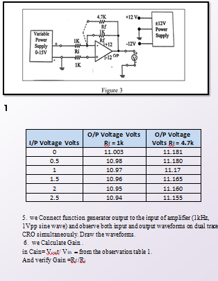
Transcribed Image Text:47K
+12 Ve
Power
Variable
Power
Supply
IK
12
-12V
Supply
0-ISV
Ri
IK
Figure 3
o/P Voltage
Volts Rj = 4.7k
O/P Voltage Volts
1/P Voltage Volts
RI = 1k
11.003
11.181
0.5
10.98
11.180
1
10.97
11.17
1.5
10.96
11.165
2
10.95
11.160
2.5
10.94
11.155
5. we Connect function generator output to the imput of amplifier (1kHz,
1Vpp sine wave) andobserve both input and output waveforms on dual trace
CRO simultaneously. Draw the waveforms.
6. we Calculate Gain.
in Cain= Veat/ Vin - from the observation table 1.
And verify Gain=Rs/Bi
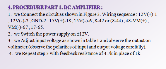
Transcribed Image Text:4. PROCEDURE PART 1. DC AMPLIFIER;
1. we Connect the circuit as shown in Figure 3. Wiring sequence: 12V(+)-1
, 12V(-)-3, GND-2,15V(+)-18,15V(-)-6,8-42 or (8-44), 48-VM(+),
VM(-)-67,17-65.
2. we Switch the power supply on ±12V.
3. we Adjust input voltage as shown in table 1 and observe the output on
voltmeter.(observe the polarities of input and output voltage carefully).
4. we Repeat step 3 with feedback resistance of 4.7k in place of 1k.
Expert Solution
This question has been solved!
Explore an expertly crafted, step-by-step solution for a thorough understanding of key concepts.

Step by step
Solved in 2 steps with 2 images

Knowledge Booster


Learn more about
Need a deep-dive on the concept behind this application? Look no further. Learn more about this topic, electrical-engineering and related others by exploring similar questions and additional content below.Recommended textbooks for you
EBK ELECTRICAL WIRING RESIDENTIAL
Electrical Engineering
ISBN:
9781337516549
Author:
Simmons
Publisher:
CENGAGE LEARNING - CONSIGNMENT
EBK ELECTRICAL WIRING RESIDENTIAL
Electrical Engineering
ISBN:
9781337516549
Author:
Simmons
Publisher:
CENGAGE LEARNING - CONSIGNMENT