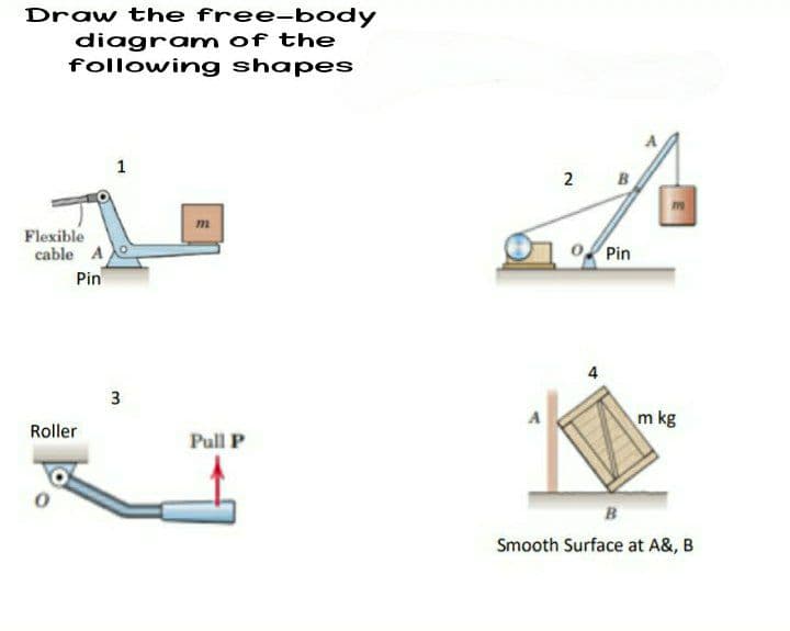
Draw the free-body diagram of the following shapes


Q: Construct a rhombus having diagonals of length 60 mm and 75 mm and measure the length of a side.
A: given; lets take diagonal length(p)=60mmlets take diagonal length(q)=75mmside(a)=?
Q: Calculate the moment at point (O) of the forces shown in figure. 30 2. m 20N 30 N
A:
Q: 2. Calculate the moment at point (G) of the forces shown in figure. AN
A:
Q: Moments and Couples 3-15. A large rock has forces acting on it as shown in Figure P3-15. Determine…
A: To Find : The moment about point A . Free body diagram : The F.B.D is shown below:
Q: Suppose beam of the list on a comer A and against a wall at the point B( No friction any surfaces)…
A:
Q: 3-7 The bending moment in the beam at point A is equal to the moment of the 800-N force about point…
A:
Q: 1. Calculate the moment at point (O) of the forces shown in figure. 10N
A: As per our guidelines we have to answer only one question. So, post the question seperately and…
Q: Calculate the moment at point C of the three forces shown in figure (clockwise + and counter…
A: The schematic diagram of the system is as follows:
Q: The figure below is a composite body consisting of the following parts: the rectangular…
A: Consider the diagram shown below.
Q: Solve for the mobility.
A:
Q: Figure Q2b shows a solid and homogeneous section, where (31.25 mm, 41.54 mm) are its centroid…
A:
Q: What would be the resultant moment of the three forces acting at the beam shown in tl figure about…
A:
Q: 2. Calculate the moment at point (G) of the forces shown in figure. 5 N.m 9m 6 m 50 2 N 3N
A:
Q: You are required to calculate the second moment of area about the x-axis for the figure below. a mm…
A: Answer: (a) The second moment of area of segment 2 about x-axis is 143676.944 mm4. (b) The second…
Q: 1. Calculate the moment at point (O) of the forces shown in figure. 10 N 30 1.5 m 2.5 m 2 m 20 N 30…
A: Note- As per our company guidelines we are supposed to answer only the first question in case of…
Q: Use the analytical method to find the resultant and its direction of the forces shown in figure 1.
A:
Q: Compute Ix and Iy for the region shown.
A:
Q: S3. Cross-sectional area of the beam given 25 mm in the figure aa according to the axis 25 mm Find…
A: Moment of Inertia:- The body that exhibits opposition to its speed of rotation about an axis is…
Q: 4- For the shaper mechanism shown in the figure, OA = 50 mm, QB = 350 mm, BC = 170 mm, OQ = 140 mm.…
A: We have to determine displacement slider 6.
Q: 3-9. Solve for the algebraic sum of the moments in pound-feet about A when h is 20 m as shown in…
A: Given data h = 20m Forces acting are 800N, 500N
Q: (b) A solid right circular cylinder has radius r and height h. A plane passes through a diameter of…
A: Volume of Cylinder = πr2h Volume of Cone = 13πr2h Volume of Remaning part = πr2h - 13πr2h = 23πr2h
Q: determine the centoidal x and y and the moment of intertia with respect to newutral axis. use the…
A:
Q: 3. Draw the free body diagram of the following figure:
A: According to the details provided in the question, we need to draw a free-body diagram of the given…
Q: 1. Calculate the moment at point (A) of the forces shown in figure. T;-10
A: Note:As per our guidelines we are supposed to answer only one question. Kindly repost other…
Q: Compute the moment about point A in the figure below
A: Consider the diagram shown below with the resolved force.
Q: Solve the problem with complete solution and draw the figure. Find the ordinate of the centroid of…
A:
Q: Solve the moment of P on points A, B, C, D. Show complete and detailed solutions. Write…
A: note = you have to find moment of p which is given as mass not force , whatever the process to…
Q: For problems 3-4 determine the angle between the two vectors. 4. a-(4.0,-3), 6-27 +107-11k
A:
Q: An 800-lb force is applied to a lever-shaft assembly as shown in Fig. 4-22. Determine the magnitude…
A:
Q: Find the centroid of the region shown in Figure
A: Divide the given area into three sections as shown in the below diagram.
Q: What is the equation for the second moment of area?
A: The second moment of the area gives the idea about how much an area is capable of resisting the…
Q: . Solve the following problem Find the centroid of the shaded body in the Figure - All dimensions…
A:
Q: Calculate the moment about point A in Figure P3-5. 800 lb 200 lb 14 3. 5'- 400 lb
A: To determine the point about Point A.
Q: 250 N 16 Calculate the moment of the 200 mm ( 300 N) force on the handle of the monkey wrench about…
A:
Q: 3-23. Determine the moment about point A due to the forces shown in Figure P3-23. 100 lb 2 60 lb 80…
A: Given question: We have to find the moment about point A. […
Q: Figure of Q4 b (m) 450 b (m)
A: As per given question The slider block C moves at 10 m/s down the inclined groove. Both links have…
Q: Calculte the moment at point A using the Varigons Theoram
A:
Q: Find the z coordinate of the centroid for the given figure. 3층 in. 3 in. 1 in. radius 2 in. radius 7…
A:
Q: 6. Determine the ratio a/b for which centroid will be located at point 'O' for a wire bent as shown…
A:
Q: Calculate the moment about point A in Figure P3-6. 800 lb 200 lb 400 lb ーブー-3- Figure P3-6
A: Moment: The moment is the product of the applied force with perpendicular distance of force from the…
Q: Determine the location of the centroid for the cross section shown below and draw a scaled sketch of…
A:
Q: For problems 3-4 determine the angle between the two vectors. 4. a=(4,0,-3), b = 27 +10j-11k
A: “Since you have asked multiple question, we will solve the first question for you. If youwant any…
Q: This airplane nose wheel assembly is raised by applying a torque M, as shown. The arm AD and the…
A: From the given data,
Q: From Figure, P is directed at an angle a from x-axis and the 200 N force is acting at a slope of 5…
A:
Q: Find the centroid for the following I section
A: Given data as per question The thickness of web =20 mm we know…
Q: blas 5 Calculate the moment at point at point (A) (Clock + and counter clock -) of the forces shown…
A: OPTION 3 IS CORRECT MA=50 KN.M
Q: Find the resultant R of the force System Shown in 40 figure. Show it's position with-respect- to…
A: TO FIND: The resultant R of the force system: Also the position with respect to the point C

Step by step
Solved in 4 steps with 4 images

- Repeat Prob. 4.152 assuming that the 400-kN force is applied at O instead of L.The 12-ft wide quarter-circular gate AB is hinged at A. Determine the contact force between the gate and the smooth surface at B due to water pressure acting on the gate. Use =62.4lb/ft3 for water.Compute the surface area of the axi-symmetric domed structure.
- The high-pressure water cock is rigidly attached to the support at D. Neglecting the weights of the members, draw the FBD of the entire assembly and count the unknowns.The plane region A is submerged in a fluid of weight density . The resultant force of the fluid pressure on the region is R acting at the point C (called the pressure center) located at the distance h below the surface of the fluid. Show that R=Qa and h=Ia/Qa, where Qa and Ia are the first and second moments of A about the axis a-a.What are the reaction forces on the latch an djoint in the gate below? And in case thefloodgate is reversed (concave)? *The gate is a cylinder room with length L = 5 m
- Consider a homogeneous right circular cylinder of lengthL , radius R , and specifi c gravity SG =0.5, fl oating in water(SG = 1). Show that the body will be stable with its axishorizontal if L / R > 2.0.The iceberg idealization may becomeunstable if its sides melt and its height exceeds its width. InFig. suppose that the height is L and the depth intothe paper is L , but the width in the plane of the paper isH , L. Assuming S =0.88 for the iceberg, fi nd the ratio H / Lfor which it becomes neutrally stable (about to overturn).The uniform rod in Fig. is hinged at point B on thewaterline and is in static equilibrium as shown when 2 kgof lead (SG = 11.4) are attached to its end. What is thespecifi c gravity of the rod material? What is peculiar aboutthe rest angle θ = 30 ° ?
- The uniform 5-m-long round wooden rod in Fig. istied to the bottom by a string. Determine ( a ) the tension inthe string and ( b ) the specifi c gravity of the wood. Is it possiblefor the given information to determine the inclinationangle θ ? Explain.The 0.5-m-radius semi-circular gate is hinged through the top edge AB. Find the required force to be applied at the center of gravity to keep the gate closed.Show the derivation of the girth and longitudinalstresses of the thin-walled cylindrical container shownbelow. Say p is the internal pressure, d is the insidediameter of the container, and t is wall thickness.