Draw the free body diagram. 80 mg 60 20 650 mm 200 925 mm mm By

Principles of Heat Transfer (Activate Learning with these NEW titles from Engineering!)
8th Edition
ISBN:9781305387102
Author:Kreith, Frank; Manglik, Raj M.
Publisher:Kreith, Frank; Manglik, Raj M.
Chapter4: Numerical Analysis Of Heat Conduction
Section: Chapter Questions
Problem 4.43P

Related questions

Question
I need a solution
Transcribed Image Text:5:11 64) * O
28
bartleby.com/questions-ai a
= bartleby
Q&A
Engineering / Mechanical Engineeri... / Q&A Libr... /
A man exerts a forec of F on the han...
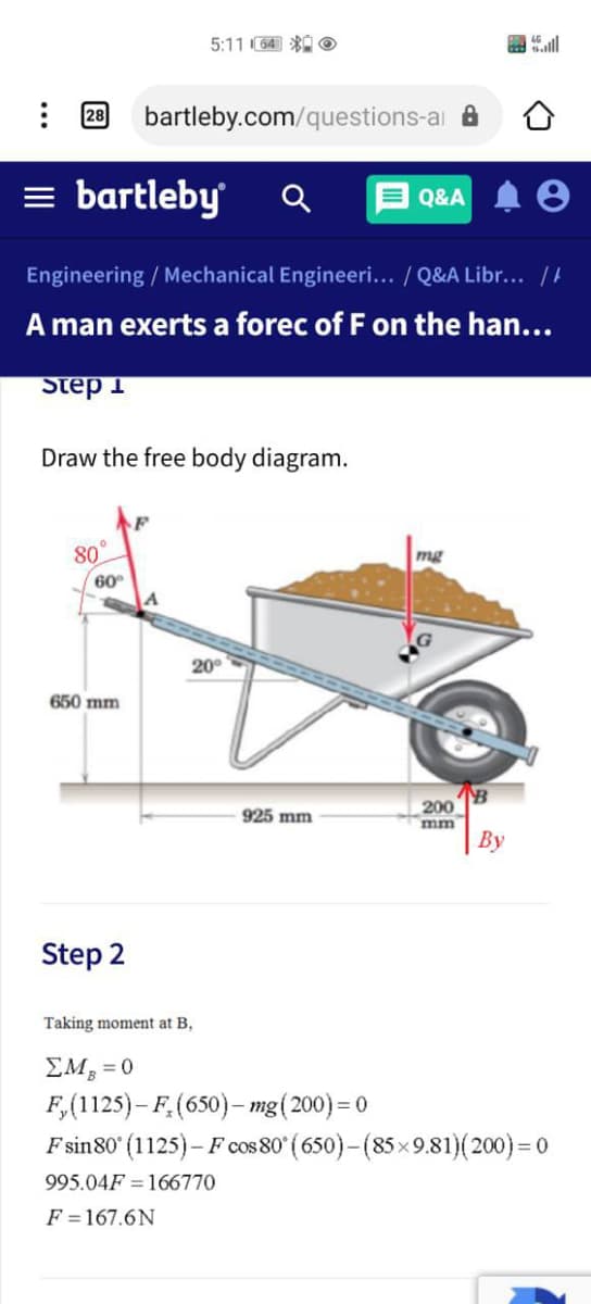
Step 1
Draw the free body diagram.
80°
60
mg
20°
650 mm
200
mm
| By
925 mm
Step 2
Taking moment at B,
EM, = 0
F,(1125)- F,(650)– mg(200)= 0
F sin80 (1125)– F cos 80° ( 650)–(85×9.81)(200) = 0
995.04F = 166770
F =167.6N
Expert Solution
This question has been solved!
Explore an expertly crafted, step-by-step solution for a thorough understanding of key concepts.

Step by step
Solved in 2 steps with 1 images

Knowledge Booster


Learn more about
Need a deep-dive on the concept behind this application? Look no further. Learn more about this topic, mechanical-engineering and related others by exploring similar questions and additional content below.Recommended textbooks for you
Principles of Heat Transfer (Activate Learning wi…
Mechanical Engineering
ISBN:
9781305387102
Author:
Kreith, Frank; Manglik, Raj M.
Publisher:
Cengage Learning
Principles of Heat Transfer (Activate Learning wi…
Mechanical Engineering
ISBN:
9781305387102
Author:
Kreith, Frank; Manglik, Raj M.
Publisher:
Cengage Learning