Draw the shear and moment diagrams for the beam shown below. 10 kN 4 kN/m 50 kN · m 5 т 3 т
Draw the shear and moment diagrams for the beam shown below. 10 kN 4 kN/m 50 kN · m 5 т 3 т

Mechanics of Materials (MindTap Course List)
9th Edition
ISBN:9781337093347
Author:Barry J. Goodno, James M. Gere
Publisher:Barry J. Goodno, James M. Gere
Chapter5: Stresses In Beams (basic Topics)
Section: Chapter Questions
Problem 5.6.13P: A two-axle carriage that is part of an over head traveling crane in a testing laboratory moves...

Related questions

Question
Transcribed Image Text:EXAMPLE
6.4
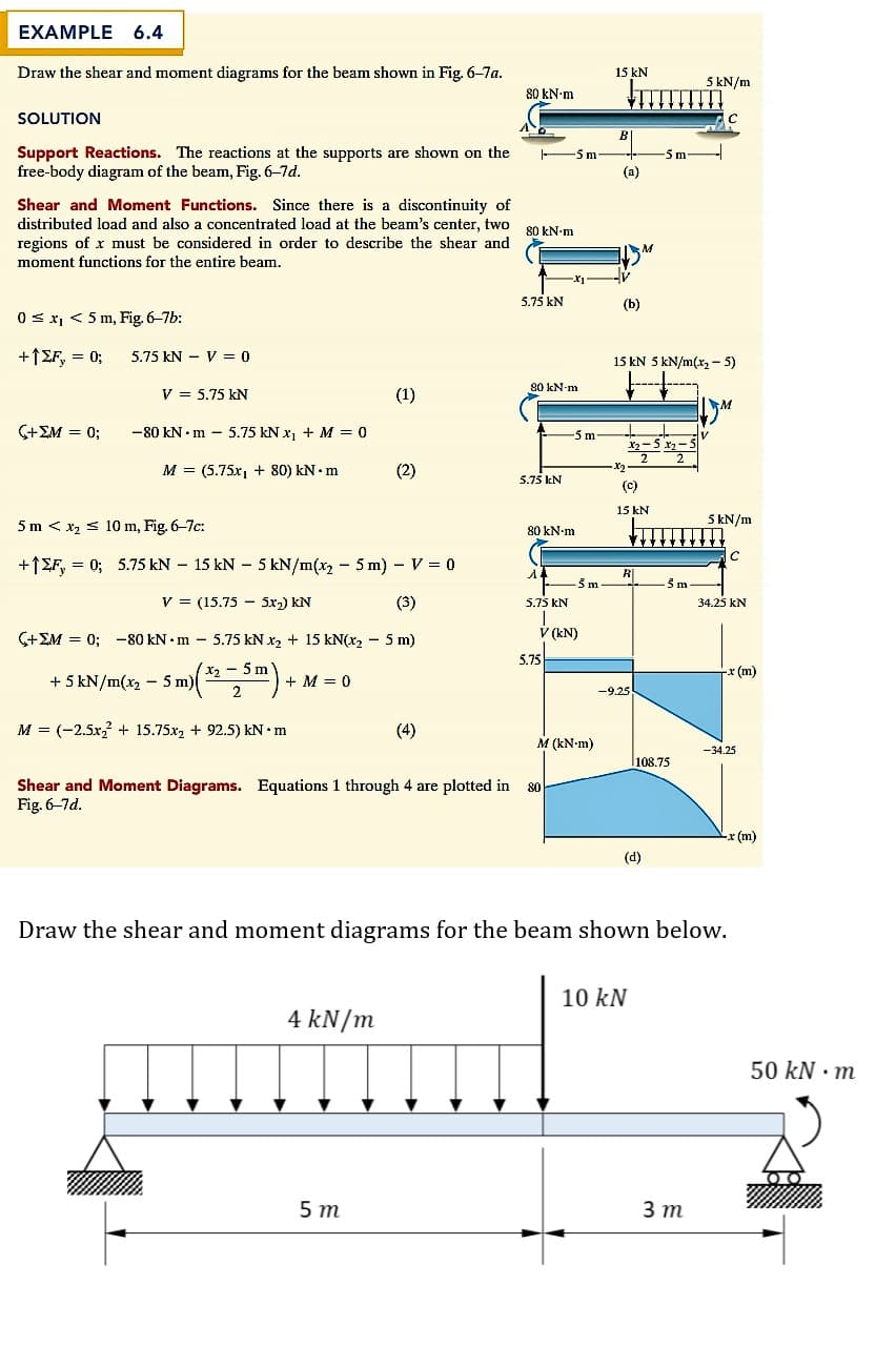
Draw the shear and moment diagrams for the beam shown in Fig. 6-7a.
15 kN
5 kN/m
80 kN-m
SOLUTION
Support Reactions. The reactions at the supports are shown on the
free-body diagram of the beam, Fig. 6-7d.
5m
-5 m
(a)
Shear and Moment Functions. Since there is a discontinuity of
distributed load and also a concentrated load at the beam's center, two 00 LNam
regions of x must be considered in order to describe the shear and
moment functions for the entire beam.
5.75 kN
(b)
0 s x, < 5 m, Fig. 6-7b:
+1£F, = 0;
5.75 kN - V = 0
15 kN 5 kN/m(x, - 5)
80 kN-m
V = 5.75 kN
(1)
(+EM = 0;
-80 kN • m – 5.75 kN x1 + M = 0
5m
-5x
M = (5.75x1 + 80) kN• m
(2)
5.75 kN
(C)
15 kN
5 kN/m
5 m < x2 s 10 m, Fig. 6-7c:
80 kN-m
+1EF, = 0; 5.75 kN – 15 kN – 5 kN/m(x, - 5 m) - V = 0
R|
V = (15.75 - 5x2) kN
(3)
5.75 kN
34.25 kN
(+EM = 0; -80 kN • m – 5.75 kN x2 + 15 kN(x2 – 5 m)
V (kN)
5.75
X2 - 5 m
x (m)
+ 5 kN/m(x2 - 5 m)
+ M = 0
-9.25
M = (-2.5x + 15.75x, + 92.5) kN •m
(4)
M (kN-m)
-34.25
l108.75
Shear and Moment Diagrams. Equations 1 through 4 are plotted in
Fig. 6-7d.
-x (m)
(d)
Draw the shear and moment diagrams for the beam shown below.
10 kN
4 kN/m
50 kN · m
5 т
3 т
Expert Solution
This question has been solved!
Explore an expertly crafted, step-by-step solution for a thorough understanding of key concepts.

This is a popular solution!

Trending now
This is a popular solution!

Step by step
Solved in 2 steps with 3 images

Knowledge Booster


Learn more about
Need a deep-dive on the concept behind this application? Look no further. Learn more about this topic, mechanical-engineering and related others by exploring similar questions and additional content below.Recommended textbooks for you
Mechanics of Materials (MindTap Course List)
Mechanical Engineering
ISBN:
9781337093347
Author:
Barry J. Goodno, James M. Gere
Publisher:
Cengage Learning
Mechanics of Materials (MindTap Course List)
Mechanical Engineering
ISBN:
9781337093347
Author:
Barry J. Goodno, James M. Gere
Publisher:
Cengage Learning