:Draw the shear force and bending moment diagram of the simply supported beam with uniformly distributed load 30kN/m.
:Draw the shear force and bending moment diagram of the simply supported beam with uniformly distributed load 30kN/m.

Chapter9: Application Of Influence Lines
Section: Chapter Questions
Problem 11P

Related questions
Question
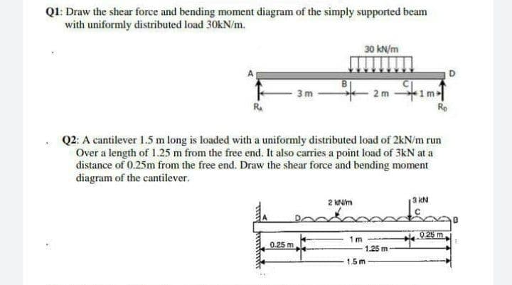
Transcribed Image Text:Q1: Draw the shear force and bending moment diagram of the simply supported beam
with uniformly distributed load 30kN/m.
30 kN/m
3m
2m
Ro
R₁
Q2: A cantilever 1.5 m long is loaded with a uniformly distributed load of 2kN/m run
Over a length of 1.25 m from the free end. It also carries a point load of 3kN at a
distance of 0.25m from the free end. Draw the shear force and bending moment
diagram of the cantilever.
3 kN
2 kN/m
0.25 m
1m
1.5m
1.25 m
0.25 m
Expert Solution
This question has been solved!
Explore an expertly crafted, step-by-step solution for a thorough understanding of key concepts.

This is a popular solution!

Trending now
This is a popular solution!

Step by step
Solved in 4 steps with 3 images

Knowledge Booster


Learn more about
Need a deep-dive on the concept behind this application? Look no further. Learn more about this topic, civil-engineering and related others by exploring similar questions and additional content below.Recommended textbooks for you