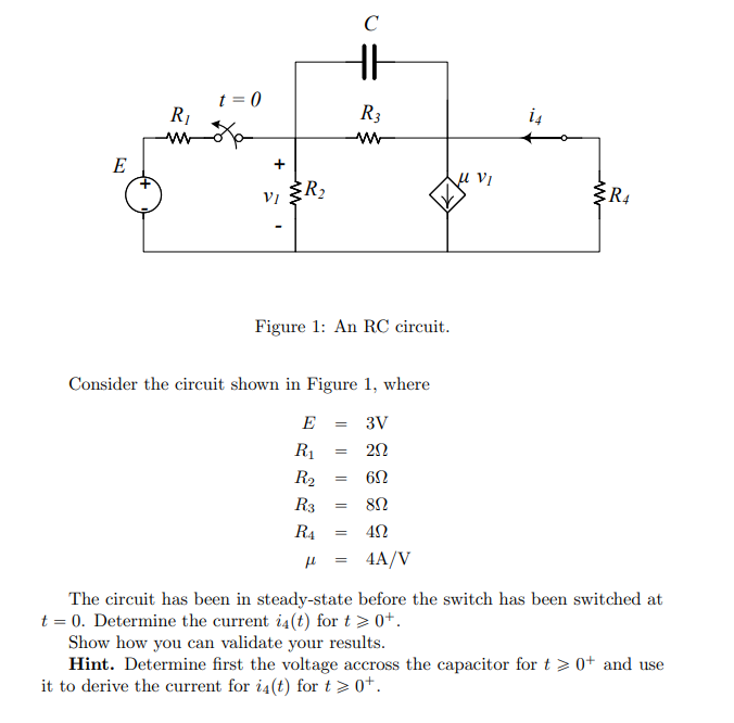
E R₁ t = 0 + VI R₂ Figure 1: An RC circuit. C HH Consider the circuit shown in Figure 1, where E = 3V R₁ = 20 R₂ R3 R4 = = R3 ww 6Ω 8Ω 40 fl 4A/V = = u Vi + R4 The circuit has been in steady-state before the switch has been switched at t = 0. Determine the current i4(t) for t > 0+. Show how you can validate your results. Hint. Determine first the voltage accross the capacitor for t> 0+ and use it to derive the current for i4(t) for t > 0+.
E R₁ t = 0 + VI R₂ Figure 1: An RC circuit. C HH Consider the circuit shown in Figure 1, where E = 3V R₁ = 20 R₂ R3 R4 = = R3 ww 6Ω 8Ω 40 fl 4A/V = = u Vi + R4 The circuit has been in steady-state before the switch has been switched at t = 0. Determine the current i4(t) for t > 0+. Show how you can validate your results. Hint. Determine first the voltage accross the capacitor for t> 0+ and use it to derive the current for i4(t) for t > 0+.

Introductory Circuit Analysis (13th Edition)
13th Edition
ISBN:9780133923605
Author:Robert L. Boylestad
Publisher:Robert L. Boylestad
Chapter1: Introduction
Section: Chapter Questions
Problem 1P: Visit your local library (at school or home) and describe the extent to which it provides literature...

Related questions
Question
The Capacitor value is 0.08 F.
Transcribed Image Text:E
R₁
t = 0
+
VI
R₂
Figure 1: An RC circuit.
C
HH
Consider the circuit shown in Figure 1, where
E = 3V
R₁
= 20
R₂
R3
R4 =
=
R3
ww
6Ω
8Ω
40
fl 4A/V
=
=
u Vi
+
R4
The circuit has been in steady-state before the switch has been switched at
t = 0. Determine the current i4(t) for t > 0+.
Show how you can validate your results.
Hint. Determine first the voltage accross the capacitor for t> 0+ and use
it to derive the current for i4(t) for t > 0+.
Expert Solution
This question has been solved!
Explore an expertly crafted, step-by-step solution for a thorough understanding of key concepts.

Step by step
Solved in 7 steps with 7 images

Knowledge Booster


Learn more about
Need a deep-dive on the concept behind this application? Look no further. Learn more about this topic, electrical-engineering and related others by exploring similar questions and additional content below.Recommended textbooks for you
Introductory Circuit Analysis (13th Edition)
Electrical Engineering
ISBN:
9780133923605
Author:
Robert L. Boylestad
Publisher:
PEARSON

Delmar's Standard Textbook Of Electricity
Electrical Engineering
ISBN:
9781337900348
Author:
Stephen L. Herman
Publisher:
Cengage Learning

Programmable Logic Controllers
Electrical Engineering
ISBN:
9780073373843
Author:
Frank D. Petruzella
Publisher:
McGraw-Hill Education
Introductory Circuit Analysis (13th Edition)
Electrical Engineering
ISBN:
9780133923605
Author:
Robert L. Boylestad
Publisher:
PEARSON
Delmar's Standard Textbook Of Electricity
Electrical Engineering
ISBN:
9781337900348
Author:
Stephen L. Herman
Publisher:
Cengage Learning
Programmable Logic Controllers
Electrical Engineering
ISBN:
9780073373843
Author:
Frank D. Petruzella
Publisher:
McGraw-Hill Education

Fundamentals of Electric Circuits
Electrical Engineering
ISBN:
9780078028229
Author:
Charles K Alexander, Matthew Sadiku
Publisher:
McGraw-Hill Education

Electric Circuits. (11th Edition)
Electrical Engineering
ISBN:
9780134746968
Author:
James W. Nilsson, Susan Riedel
Publisher:
PEARSON

Engineering Electromagnetics
Electrical Engineering
ISBN:
9780078028151
Author:
Hayt, William H. (william Hart), Jr, BUCK, John A.
Publisher:
Mcgraw-hill Education,