For the following figure, if Rx=1466.66. Assuming that the diode is ideal and the input impedance of the voltmeter is infinite, the readinglof the voltmeter is: Rx 100k (v}14.14sin (314t) Voltmeter Select one: O-4.44 O-1.39 4.14 -1.4 O-13.94
For the following figure, if Rx=1466.66. Assuming that the diode is ideal and the input impedance of the voltmeter is infinite, the readinglof the voltmeter is: Rx 100k (v}14.14sin (314t) Voltmeter Select one: O-4.44 O-1.39 4.14 -1.4 O-13.94

Delmar's Standard Textbook Of Electricity
7th Edition
ISBN:9781337900348
Author:Stephen L. Herman
Publisher:Stephen L. Herman
Chapter16: Inductance In Ac Circuits
Section: Chapter Questions
Problem 2PP: What frequency must be applied to a 33-mH inductor to produce an inductive reactance of 99.526 ?

Related questions
Question
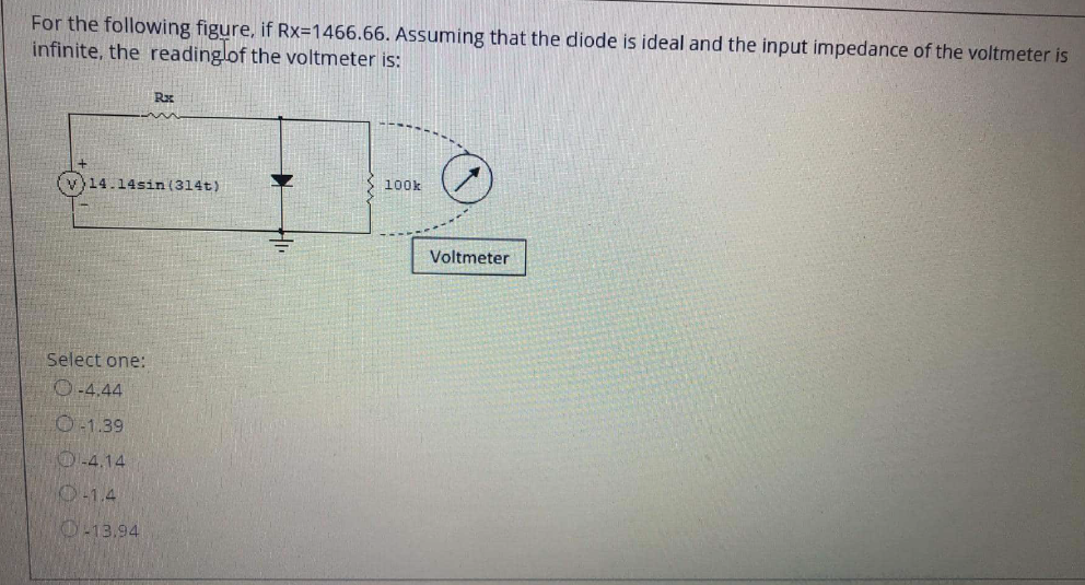
Transcribed Image Text:For the following figure, if Rx=1466.66. Assuming that the diode is ideal and the input impedance of the voltmeter is
infinite, the readinglof the voltmeter is:
Rx
100k
(v}14.14sin (314t)
Voltmeter
Select one:
O-4.44
O-1.39
4.14
-1.4
O-13.94
Expert Solution
This question has been solved!
Explore an expertly crafted, step-by-step solution for a thorough understanding of key concepts.

Step by step
Solved in 2 steps with 1 images

Recommended textbooks for you
Delmar's Standard Textbook Of Electricity
Electrical Engineering
ISBN:
9781337900348
Author:
Stephen L. Herman
Publisher:
Cengage Learning
Delmar's Standard Textbook Of Electricity
Electrical Engineering
ISBN:
9781337900348
Author:
Stephen L. Herman
Publisher:
Cengage Learning