(9) The Bode diagram of the open-loop transfer function G(s) of a unity feedback control system is obtained experimentally and is shown below when its loop gain K is set at its nominal value, Ko. 1. Find the gain and phase margins of the system from the diagram as best you can read. Also find the gain and phase crossover frequencies. Gain crossover frequency @₁ = Phase crossover frequency 02 = GM = PM = 2. Repeat part (1) if the loop gain K is 10 times its nominal value (i.e., K = 10 Ko). Gain crossover frequency @₁ = Phase crossover frequency o2 = GM= PM = 3 Find out how much the loop gain K must be changed from its nominal value Ko (i.e., K = a Ko) if the gain margin is to be 40 dB. α = 4 Find out how much the loop gain K must be changed from its nominal value Ko (i.e., K = BK) if the phase margin is to be 45°. В 60 40 1.0 1000 | G(jw) | (dB) ZG(jw) (deg) 20 0 -20 -40 -60 -80 -100 -120 0.01 0 -45 -90 -135 -180 -225 -270 0.01 0.1 0.1 1.0 w (rad/sec) w (rad/sec) 10 10 100 100 1000
(9) The Bode diagram of the open-loop transfer function G(s) of a unity feedback control system is obtained experimentally and is shown below when its loop gain K is set at its nominal value, Ko. 1. Find the gain and phase margins of the system from the diagram as best you can read. Also find the gain and phase crossover frequencies. Gain crossover frequency @₁ = Phase crossover frequency 02 = GM = PM = 2. Repeat part (1) if the loop gain K is 10 times its nominal value (i.e., K = 10 Ko). Gain crossover frequency @₁ = Phase crossover frequency o2 = GM= PM = 3 Find out how much the loop gain K must be changed from its nominal value Ko (i.e., K = a Ko) if the gain margin is to be 40 dB. α = 4 Find out how much the loop gain K must be changed from its nominal value Ko (i.e., K = BK) if the phase margin is to be 45°. В 60 40 1.0 1000 | G(jw) | (dB) ZG(jw) (deg) 20 0 -20 -40 -60 -80 -100 -120 0.01 0 -45 -90 -135 -180 -225 -270 0.01 0.1 0.1 1.0 w (rad/sec) w (rad/sec) 10 10 100 100 1000

Power System Analysis and Design (MindTap Course List)
6th Edition
ISBN:9781305632134
Author:J. Duncan Glover, Thomas Overbye, Mulukutla S. Sarma
Publisher:J. Duncan Glover, Thomas Overbye, Mulukutla S. Sarma
Chapter12: Power System Controls
Section: Chapter Questions
Problem 12.3P

Related questions

Concept explainers
KVL and KCL
KVL stands for Kirchhoff voltage law. KVL states that the total voltage drops around the loop in any closed electric circuit is equal to the sum of total voltage drop in the same closed loop.
Sign Convention
Science and technology incorporate some ideas and techniques of their own to understand a system skilfully and easily. These techniques are called conventions. For example: Sign conventions of mirrors are used to understand the phenomenon of reflection and refraction in an easier way.
Question
9
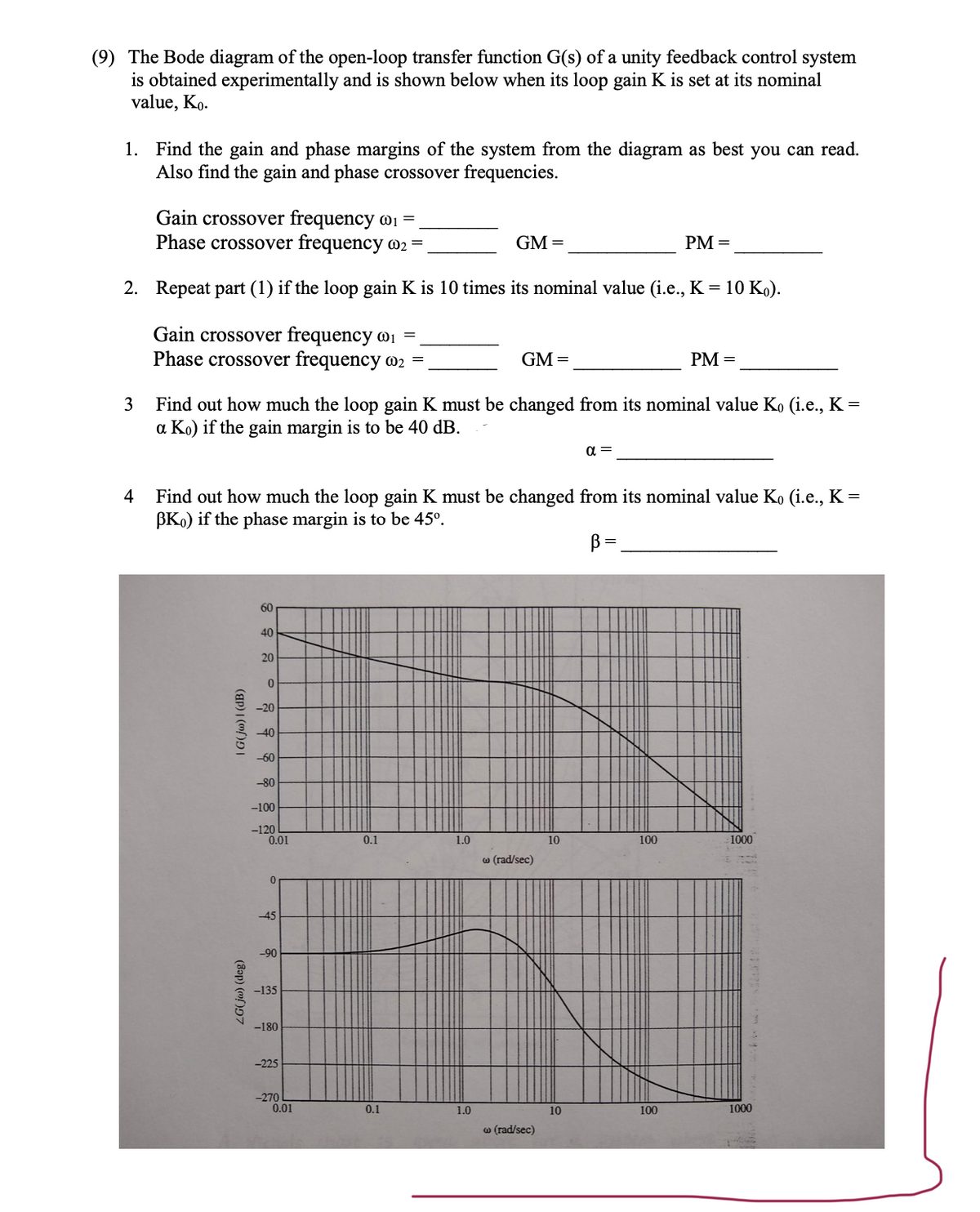
Transcribed Image Text:(9) The Bode diagram of the open-loop transfer function G(s) of a unity feedback control system
is obtained experimentally and is shown below when its loop gain K is set at its nominal
value, Ko.
1. Find the gain and phase margins of the system from the diagram as best you can read.
Also find the gain and phase crossover frequencies.
Gain crossover frequency @₁ =
Phase crossover frequency 02 =
GM =
PM =
2. Repeat part (1) if the loop gain K is 10 times its nominal value (i.e., K = 10 Ko).
Gain crossover frequency @₁ =
Phase crossover frequency o2 =
GM=
PM =
3
Find out how much the loop gain K must be changed from its nominal value Ko (i.e., K =
a Ko) if the gain margin is to be 40 dB.
α =
4
Find out how much the loop gain K must be changed from its nominal value Ko (i.e., K =
BK) if the phase margin is to be 45°.
В
60
40
1.0
1000
| G(jw) | (dB)
ZG(jw) (deg)
20
0
-20
-40
-60
-80
-100
-120
0.01
0
-45
-90
-135
-180
-225
-270
0.01
0.1
0.1
1.0
w (rad/sec)
w (rad/sec)
10
10
100
100
1000
Expert Solution
This question has been solved!
Explore an expertly crafted, step-by-step solution for a thorough understanding of key concepts.

This is a popular solution!

Trending now
This is a popular solution!

Step by step
Solved in 3 steps with 3 images

Knowledge Booster


Learn more about
Need a deep-dive on the concept behind this application? Look no further. Learn more about this topic, electrical-engineering and related others by exploring similar questions and additional content below.Recommended textbooks for you
Power System Analysis and Design (MindTap Course …
Electrical Engineering
ISBN:
9781305632134
Author:
J. Duncan Glover, Thomas Overbye, Mulukutla S. Sarma
Publisher:
Cengage Learning
Power System Analysis and Design (MindTap Course …
Electrical Engineering
ISBN:
9781305632134
Author:
J. Duncan Glover, Thomas Overbye, Mulukutla S. Sarma
Publisher:
Cengage Learning