Electronic In the circuit in the figure, Vi = 20 mV, VCC = 15 V, β = 110, r0 = 30 kΩ, RC = 4.7 kΩ, RF1 = 100 kΩ, RF2 = 47 kΩ. Also, since the internal resistance of the ac source is RS = 1.07 kΩ and the load connected to the output is RL = 22.3 kΩ, what is the value of the output voltage (V0)? NOTE: The output impedance of the transistor r0 must be taken into account in the calculations.
Electronic In the circuit in the figure, Vi = 20 mV, VCC = 15 V, β = 110, r0 = 30 kΩ, RC = 4.7 kΩ, RF1 = 100 kΩ, RF2 = 47 kΩ. Also, since the internal resistance of the ac source is RS = 1.07 kΩ and the load connected to the output is RL = 22.3 kΩ, what is the value of the output voltage (V0)? NOTE: The output impedance of the transistor r0 must be taken into account in the calculations.

Introductory Circuit Analysis (13th Edition)
13th Edition
ISBN:9780133923605
Author:Robert L. Boylestad
Publisher:Robert L. Boylestad
Chapter1: Introduction
Section: Chapter Questions
Problem 1P: Visit your local library (at school or home) and describe the extent to which it provides literature...

Related questions
Question
Electronic
In the circuit in the figure, Vi = 20 mV, VCC = 15 V, β = 110, r0 = 30 kΩ, RC = 4.7 kΩ, RF1 = 100 kΩ, RF2 = 47 kΩ. Also, since the internal resistance of the ac source is RS = 1.07 kΩ and the load connected to the output is RL = 22.3 kΩ, what is the value of the output voltage (V0)? NOTE: The output impedance of the transistor r0 must be taken into account in the calculations.
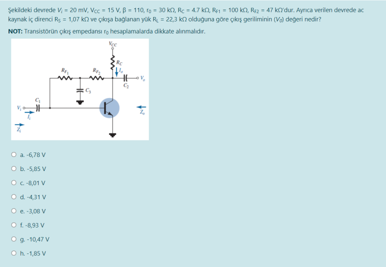
Transcribed Image Text:Şekildeki devrede V; = 20 mV, Vcc = 15 V, B = 110, ro = 30 k, Rc = 4.7 kN, Rfj = 100 kO, RĘ2 = 47 kQ'dur. Ayrıca verilen devrede ac
kaynak iç direnci Rs = 1,07 k2 ve çıkışa bağlanan yük RL = 22,3 kN olduğuna göre çıkış geriliminin (Vo) değeri nedir?
NOT: Transistörün çıkış empedansı ro hesaplamalarda dikkate alınmalıdır.
RC
RE
O a. -6,78 V
O b. -5,85 V
O .-8,01 V
O d.-4,31 V
O e. -3,08 V
O f. -8,93 V
O g. -10,47 V
O h. -1,85 V
Expert Solution
This question has been solved!
Explore an expertly crafted, step-by-step solution for a thorough understanding of key concepts.

Step by step
Solved in 3 steps with 3 images

Knowledge Booster


Learn more about
Need a deep-dive on the concept behind this application? Look no further. Learn more about this topic, electrical-engineering and related others by exploring similar questions and additional content below.Recommended textbooks for you
Introductory Circuit Analysis (13th Edition)
Electrical Engineering
ISBN:
9780133923605
Author:
Robert L. Boylestad
Publisher:
PEARSON

Delmar's Standard Textbook Of Electricity
Electrical Engineering
ISBN:
9781337900348
Author:
Stephen L. Herman
Publisher:
Cengage Learning

Programmable Logic Controllers
Electrical Engineering
ISBN:
9780073373843
Author:
Frank D. Petruzella
Publisher:
McGraw-Hill Education
Introductory Circuit Analysis (13th Edition)
Electrical Engineering
ISBN:
9780133923605
Author:
Robert L. Boylestad
Publisher:
PEARSON
Delmar's Standard Textbook Of Electricity
Electrical Engineering
ISBN:
9781337900348
Author:
Stephen L. Herman
Publisher:
Cengage Learning
Programmable Logic Controllers
Electrical Engineering
ISBN:
9780073373843
Author:
Frank D. Petruzella
Publisher:
McGraw-Hill Education

Fundamentals of Electric Circuits
Electrical Engineering
ISBN:
9780078028229
Author:
Charles K Alexander, Matthew Sadiku
Publisher:
McGraw-Hill Education

Electric Circuits. (11th Edition)
Electrical Engineering
ISBN:
9780134746968
Author:
James W. Nilsson, Susan Riedel
Publisher:
PEARSON

Engineering Electromagnetics
Electrical Engineering
ISBN:
9780078028151
Author:
Hayt, William H. (william Hart), Jr, BUCK, John A.
Publisher:
Mcgraw-hill Education,