EVA, a = 10:1,60-Hz,

Power System Analysis and Design (MindTap Course List)
6th Edition
ISBN:9781305632134
Author:J. Duncan Glover, Thomas Overbye, Mulukutla S. Sarma
Publisher:J. Duncan Glover, Thomas Overbye, Mulukutla S. Sarma
Chapter3: Power Transformers
Section: Chapter Questions
Problem 3.58P: A single-phase two-winding transformer rated 90MVA,80/120kV is to be connected as an autotransformer...

Related questions
Question
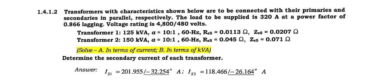
Transcribed Image Text:Transformers with characteristics shown below are to be connected with their primaries and
secondaries in parallel, respectively. The load to be supplied is 320 A at a power factor of
0.866 lagging. Voltage rating is 4,800/480 volts.
Transformer 1: 125 kVA, a = 10:1 , 60-Hz, Res
Transformer 2: 150 kVA, a = 10:1 , 60-Hz, Res = 0.045 Q, Zes
1.4.1.2
0.0113 Q, Zes = 0.0207 2
%3D
0.071 2
%3D
%D
(Solve - A. In terms of current; B. In terms of kVA)
Determine the secondary current of each transformer.
Answer:
Isi = 201.955/-32.254° A; I2 =118.466/-26.164° A
%3D
%3D
Expert Solution
This question has been solved!
Explore an expertly crafted, step-by-step solution for a thorough understanding of key concepts.

Step by step
Solved in 3 steps with 3 images

Knowledge Booster


Learn more about
Need a deep-dive on the concept behind this application? Look no further. Learn more about this topic, electrical-engineering and related others by exploring similar questions and additional content below.Recommended textbooks for you
Power System Analysis and Design (MindTap Course …
Electrical Engineering
ISBN:
9781305632134
Author:
J. Duncan Glover, Thomas Overbye, Mulukutla S. Sarma
Publisher:
Cengage Learning

Delmar's Standard Textbook Of Electricity
Electrical Engineering
ISBN:
9781337900348
Author:
Stephen L. Herman
Publisher:
Cengage Learning

EBK ELECTRICAL WIRING RESIDENTIAL
Electrical Engineering
ISBN:
9781337516549
Author:
Simmons
Publisher:
CENGAGE LEARNING - CONSIGNMENT
Power System Analysis and Design (MindTap Course …
Electrical Engineering
ISBN:
9781305632134
Author:
J. Duncan Glover, Thomas Overbye, Mulukutla S. Sarma
Publisher:
Cengage Learning
Delmar's Standard Textbook Of Electricity
Electrical Engineering
ISBN:
9781337900348
Author:
Stephen L. Herman
Publisher:
Cengage Learning
EBK ELECTRICAL WIRING RESIDENTIAL
Electrical Engineering
ISBN:
9781337516549
Author:
Simmons
Publisher:
CENGAGE LEARNING - CONSIGNMENT