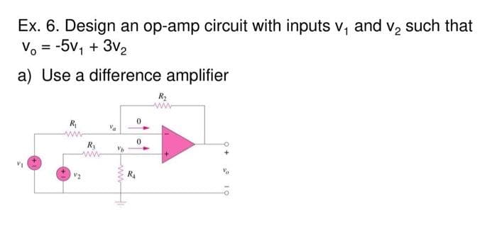
Ex. 6. Design an op-amp circuit with inputs v, and v, such that Vo = -5v, + 3v2 a) Use a difference amplifier R2 R ww-


Q: Asume that the op-amp in the circuit shown is ideal. Find vo, io, i, and iz for the circuit shown in…
A:
Q: R, For the circuit shown, R • R = 22 kQ The op-amp is ideal. Find the value of R2 required so that…
A:
Q: 1. Design an inverting-summing amplifier using a 120 kΩ resistor in the feedback path so that…
A: Since you have asked multiple question, we will solve the first question for you. If you want any…
Q: H.W. 2: Design an inverting op-amp circuit for which the gain is -10 and the to resistance used is…
A:
Q: 4. (a). (b). Operational amplifiers (op-amps) are used in integrated circuits for signal…
A: Given a circuit of an operational amplifier as shown below. Find State characteristic of the ideal…
Q: Semi-ideal OpAmps – If we have an opamp with FINITE gain A, solve for the voltage gain Vout/Vin.…
A: Given semi-ideal op-amp circuit shown VOUT=AV+-V-
Q: (a) What op amp circuit configuration is this? (b) Derive an expression for the output voltage vo in…
A:
Q: Consider the circuit shown, use an ideal op amp model to get the vo : -f(R, Δr) expression for the…
A: We need to find given voltage relation for given circuit
Q: Design a summing amplifier which has two voltage sources, namely Vị and V2. The output voltage of…
A: Given, To design a summing amplifier which has two voltage sources, namely V1 and V2. The output…
Q: Given: R, v1; Vo- Assume that the op-amp is ideal. Determine v2. R 8 k2 8 k2 R
A: In the question, assume ideal op amplifier with negative feedback. Find the voltage V2 if R1=9k…
Q: For the below given circuit : 1) Write the Name of the amplifiers 1, 2 and 3. 2) Closed loop gains…
A: All the operational amplifiers are ideal. Virtual short concept is valid. According to the virtual…
Q: Using Op-Amps, design circuits to perform following mathematical operations: a. Vout = 2V, +…
A: We have to design op-amp circuits to provide the following mathematical operations, (a). Voutput =…
Q: For the circuit shown, R, R1 = 560 Q R2 = 8.2 k2 The op-amp is ideal. If the input voltage is v; =…
A: Given op amp is an ideal op amp So we can use the concept of virtual ground Virtual ground means…
Q: ov- -5V- V(vo1) 12V- ov -12V V(v2) V(vnoise) 5V- -5V- V(vo2) 12V
A: Due to the presence of noise as it can be seen from the simulation diagram given the output v01,…
Q: Which of the following characteristics does not necessarily apply to an op amp?
A: 6. Which of the following characteristics does not necessarily apply to an op amp?a. high gainb.…
Q: Consider the circuit shown, use an ideal op amp model to get the vo expression for the gain, =f(R,…
A: We need to find voltage ratio for given circuit .
Q: Consider the circuit shown, use an ideal op amp model to get the VO expression for the gain, · =…
A: ideal operational amplifier is infinity input impedance and zero output impedance and the open loop…
Q: TUTORIAL - Op-Amp Q6 Find the range of output voltage V. developed in the circuit of Fig. 6. = 0.5 V…
A:
Q: In this circuit mown, use an ideal op amp mo del to gat the exprosion R V. V. %3D Ve for the gain, =…
A: Solve the above question
Q: Give me a real-life application of an Inverting OP-AMP(Operational Amplifier) and a solution on how…
A:
Q: oVo Rz 3 R4 R3 For the op amp cúrcuit shown: is Find the voltage gain Vo/Vi" ii) Select the resistor…
A:
Q: Question 1: a) Design a non-inverting amplifier using an ideal op amp that has a gain 7.5. b) If you…
A: (a) A non-inverting amplifier design using an ideal op amp having a gain of Av=7.5. For an ideal…
Q: Given Vdc =10 V in the circuit below, what is the maximum value of R that can be used for this…
A:
Q: how do i design this op amps so that i can get an overall gain of -8? and how do i find the values…
A:
Q: For the op amp circuit given below, the op amp has an open-loop gain of 80000, an input resistance…
A: Given data: open loop gain = 800000 input resistance = 9k ohm output resistance = 140 ohm
Q: For the circuit shown, • R = 22 kN R2 • R2 = 180 k2 R, The op-amp is ideal. Determine the…
A:
Q: A single-pole op amp has an open-loop gain of 95 dB and a unity-gain frequency of 2 MHz. (a) The op…
A: Given f=2 MHz Calculating angular frequency ωT=2πfωT=2π2 MHzωT=4×10⁶ π
Q: 4. Verify Vout of the op-amp circuit in term of inputs V1 and V2. Assume the op-amp is ideal. Vout R…
A: Determine Vout in terms of V1&V2 for the given amplifier ?
Q: For ideal op amp operating with the following feedback network in the non-inverting configuration,…
A: Non-Inverting Opamp gain is given by A= 1+(R2/R1) and that of inverting opamp has gain = (-R2/R1)…
Q: Q3. For the op-amp circuit shown below, find the value of vo, where R1 = 20 2, R2 = 12 2, R3 = 15 Q,…
A:
Q: The op-amp circuit shown below is: R1 R2 V1 R3 Vout Vz o W +, R4 O a. An inverting amplifier circuit…
A:
Q: Design an inverting circuit using a single operational amplifier that produces an output, vo =-(8V1…
A:
Q: The following circuit uses an op-amp that is ideal except for having a finite open-loop gain A.…
A: Given data: Vo=4 VV1=1 V
Q: sume that the op-amp in the circuit shown is ideal. Finc figure below. 2ΚΩ 4 ΚΩ 20 V 10KNS
A:
Q: 5.10 For the circuit involving an ideal op amp shown in the image below, if R1 = 10 k2 and R2 = 11…
A:
Q: Derive the voltage gain of the circuit given, assuming it is an Ideal Op- Amp. If R1=2k, R2=10K2 and…
A:
Q: (a) Illustrate the difference between an operational amplifier's practical equivalent model and its…
A:
Q: a. Use the Ideal Op Amp model to predict the output voltage Vout in terms of va and vp in three…
A:
Q: Design a summing amplifier which has two voltage sources, namely Vi and V2. The output voltage of…
A:
Q: For the op amp circuit, find the voltage gain vo/vs. assume R1= 100 ohms, R2= 150 ohms, Rf= 500 ohms
A: The solution can be achieved as follows.
Q: R + R R R-Ar R vo Find the expression for the gain, = f(R, Ar), using an ideal op amp model. vs
A:
Q: 2) Consider the following op-amp circuit, which contains one resistor (of resistance R), and one…
A:
Q: 1. Consider the ideal op-amp circuit below. Let Us = 0.1 V, R1 = R2 = R3 = Rz = 100 k2, and R4 = 98…
A: We know that for an ideal Op-amp the potential of inverting and non inverting terminal are same. The…
Q: 2R The input resistance of the circuit shown in the figure, assuming an ideal op amp, is R 3R Ve
A: Given circuit is - Given that op-amp is ideal.
Q: Design a noninverting amplifier with a nominal gain of 4, a gain error of 0,7%, and a total…
A:
Q: vo Use and ideal op-amp model to get the expression for the gain, vs = f(R, Ar) R + + + + R R V.…
A: According to policy i will answer only 1st question. To find gain, Vo/Vs = ? Given ideal op-amp
Q: Asume that the op-amp in the circuit shown is ideal. Find vo, io, in and iz for the circuit shown in…
A:
Q: Design a two-stage OP AMP circuit consisting of an inverting amplifier connected to a summing…
A: As mentioned in question, we need to just design the 2 stage opamp circuit as given.
Q: For the below given circuit: 1) Write the Name of the amplifiers 1, 2 and 3. 2) Closed loop gains…
A:

Step by step
Solved in 2 steps with 1 images

- Derive the appropriate equation for an inverting amplifier with op-amp and provide the values of resistances to obtain the gain equal 3 (kvR -> infinity, Vr -> 0)For the op-amp circuit shown below, find the value of vO, where R1 = 19 Ω, R2 = 14 Ω, R3 = 18 Ω, R4 = 14 Ω, Rf = 11 Ω, VS1 = 15 V, and VS2 = 3 V.Consider the active circuit with the schematic:a. Assuming it's an ideal op amp, derive the circuit’s transfer function as a function of frequency, H(jw). Make sure it in canonical form.b. We want a DC gain of 40dB. If the op amp has value of Rin = 10MΩ and Rout = 50Ω, choose appropriate values for R1 and R2. Explain why your selected values of R1 and R2 allow you to ignore Rin and Rout for the remainder of the problem. c. If L = 1H, sketch the straight-line approximation of the Bode plot for the circuit’s gain assuming the op amp can still be considered as ideal.d. The op amp you select turns out to be non-ideal, and it has a real pole at wC = 1krad/s. Write the updated transfer function for your circuit (using your values of R1, R2, and L = 1H). Make it in the canonical form.e. Sketch the straight-line approximation of the Bode plot for the circuit with your updated transfer function from D.
- Consider the active circuit with the schematic:a. Assuming it's an ideal op amp, derive the circuit’s transfer function as a function of frequency, H(jw). Make sure it in canonical form.b. We want a DC gain of 40dB. If the op amp has value of Rin = 10MΩ and Rout = 50Ω, choose appropriate values for R1 and R2. Explain why your selected values of R1 and R2 allow you to ignore Rin and Rout for the remainder of the problem.Based on the simulation’s results, explain the function of a differential amplifier. (Hints: comment on the shape of Vo1 and Vo2, explain what would happen if V1 and V2 were the same, reflect on why it is important that an ideal op-amp has infinite input impedance).Suppose the op amp shown has an fT of 3 MHz. What is the phase margin of the amplifier?
- Consider the following op amp configuration.(a) Choose R2 such that the ideal voltage gain is Av = 40dB and draw the amplifier’stransfer characteristic.(b) Find the amplifier’s input and output resistances.(c) If the op amp’s internal gain is Ao = 120dB, what is the expected voltage gain ofthe entire network?A non-inverting op-amp circuit has the open loop gain of 104 and the resistances R1 = 2k Ω and R2 = 50 k Ω. Calculate (a) The actual value of voltage gain (b) Considering the finite open loop gain, the ideal value of gain, and (c) The percentage error, when ideal voltage gain is compared with actual voltage gain.For the circuit given, a) Find VO in terms of V1 and V2. b) If V1=2V and V2=6V, find VO. c) If the op-amp supplies are ±12V, and V1=4V, what is the allowable range of V2?
- Given circuit shown below, assume ideal components. Find the value of IA and resistor, R. What is the output current of the op-amp, IO?An ideal op-amp circuit is shown above, with dc supply Vcc = -Vcc = 12V. Assume that vs = 3V, R1 = 2Ω, Rf = 4Ω. Please find the output voltage vo in volts.Get the following:gain of a non-inverting amplifier - Avoutput voltage - Vovoltage at the non-inverting and inverting input of an op-amp - V+ , V-