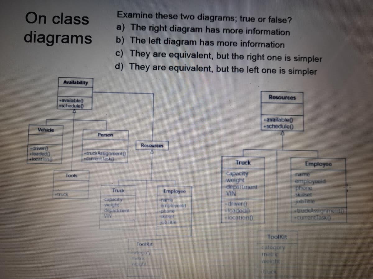
Examine these two diagrams; true or false? a) The right diagram has more information b) The left diagram has more information c) They are equivalent, but the right one is simpler d) They are equivalent, but the left one is simpler
Q: lease help me with the response diagram
A: Consider the following JAVA code :-
Q: ake a diagram or figures that shows high cohesion and loose coupling
A:
Q: To represent processes, a traditional structured design uses ... .. of diagrams
A: A traditional organizational structure follows a system in which power flows upward through the…
Q: Use UML state diagrams to construct a rudimentary representation of the Student Information System's…
A: Introduction: The significance of the UML diagram for a student management system is that it…
Q: Draw the Class Diagram for the Described System.
A: The given problem is related to UML designing where the class names and associations of the classes…
Q: Explain the difference in both diagrams? Name the mechanism which is used here?
A: Both are instruction processing algorithm which comes under the concept of Operating System. Diagram…
Q: It's important to explain the difference between the diagrams 0. Is there a symbol in the Context…
A: Difference The relationship between the context diagram and diagram 0 is as follows: The context…
Q: 5 intelligent questions about this diagram with answer
A: By Observing the figure It is clear that it comes from amazon web services. Q1. List out some…
Q: 12. UML sequence diagram is one of the diagrams that model* O The user view of a system O The…
A: UML provides the standard way to visualize the design of a system. Unified Modeling Language (UML)…
Q: It's crucial to describe the variations between Diagrams 0 and 1. Does the Context diagram include…
A: The distinction between the context diagram and diagram 0The context diagram presents a number of…
Q: write explanantion of this erd diagram
A: write explanantion of this erd diagram?
Q: 18. Draw vertical lines to delineate the working set(s) in this diagram: time
A: The solution for the above given question is given below:
Q: reate a case diagram in the picture provide
A: The given problem is related to UML Designing where the data flow diagram is given and the use case…
Q: Compare a state machine diagram with a sequence diagram and discuss the differences between the two
A: What is State Diagram? A state diagram (also called state machine diagram, statechart and start…
Q: The two types of interaction diagrams are _____ diagrams. Which is correct? A. use case and…
A: Please find the answer below :
Q: What is the importance of drawing a Hasse Diagram to represent a POSET? Use your own word and give…
A: So, first, we will know what is a Hasse Diagram? :- so, It is a Graphical Representation of the…
Q: omputer Science Draw an Entity Relationship Diagram of an insulin pump
A: Insulin pump system is used to calculate how much amount of insulin is required to be injected in a…
Q: Refer to the figure above, then answer all questions: 1. What is the name of this diagram type, and…
A: The diagram type is DFD (Data Flow Diagram). DFD consists of entities and flow of data among those…
Q: Create a State Diagram for an old western shooting video game. With all the proper components…
A: I have designed a Use Case Diagram for a wester shooting game but you can add more features to it.…
Q: With the help of diagrams explain your understanding of proper and improper handoffs
A: With the help of diagrams explain your understanding of proper and improper handoffs.
Q: What is visibility in OOAD? Describe its role in obtaining high abstraction. What are the various…
A: OOAD stands for Object-oriented analysis and design. Visibility in OOAD: Visibility allows to…
Q: Darw class diagram ,context diagram, 2sequence diagrams and use case diagram for a school nursery
A: Below it is drawn:
Q: Convert the below ER diagram to class diagram by using Argo UML
A: Class diagram for given schema diagram is as follows :
Q: The above diagram in figure represents a diagram. workflow state sequence use case
A: Below is the complete solution with explanation in detail for the given question.
Q: Verity the truth table for the three-variable exclusive-OR function of the given diagram. List all…
A: Given logic diagram contains, 3 Input variables= {A, B, C} Output variable= X The output of the XOR…
Q: The term Incomplete for a UML has the same meaning as which of the following for an EER diagram
A: This question tells about the term Incomplete for a UML has the same meaning as which of the…
Q: features and classifications in detail also discuss the implications of Moore’s Law with the help of…
A: The scaling theory concentrates on a qualitative understanding of universal features of polymer…
Q: Identify the problems in the below given diagrams. You will get extra marks for identifying…
A: Please give positive ratings for my efforts. Thanks. ANSWER Below are the problems present on…
Q: ase check if my mistake in the diagram is correct or you can add more if there is more
A: It is defined as the main building blocks of every object-oriented method. The class diagram can be…
Q: UML DIAGRAM convert class diagram to use case diagram
A: In the above problem, we need to design the Activity diagram of the Provided class diagram Please…
Q: iagrams types for describing dynamic models: StateChart diagrams and Interaction diagrams. Let’s…
A: It is defined as UML (Unified Modeling Language) is a standard language for specifying, visualizing,…
Q: Draw state stable and diagram for below diagram.
A:
Q: May I know is context diagram same as UML diagram(use case diagram)?
A: The context diagram and the use case diagrams both are different. Use case diagram using UML is…
Q: a. What does the arrow labelled (vii) signify? b. What does the dashed line labelled (viii)…
A: The given problem is related to UML sequence diagram where the requirement is to identify the…
Q: Is a self-transition required in every State Diagram? Why do you think that is the case?
A: HERE IS THE ANSWER:
Q: 5. Compare and contrast between Activity Diagrams, Sequence Diagrams, Class Diagrams, and State…
A: Given: Explain Activity Diagram, Sequence Diagram, Class Diagram, State Machine Diagram.
Q: Create an activity on arrow diagram based on the following information:
A: Solution:
Q: Draw a state diagram for a design tool like Figma,
A: According to the question we need to draw a state diagram for a design tool like Figma, draw clearly…
Q: crowsfoot diagram
A: ANSWER: Crows Foot: Crows foot diagrams address elements as boxes, and connections as lines between…
Q: Explain with the aid of examples ,
A: Model: A model is an abstraction that contains all the elements needed to explain the intention of…
Q: What is a ladder diagram? What does it symbolize?
A: Ladder diagram: Ladder diagrams are specialized symbolic and simplified diagrams that are commonly…
Q: diagram models the .12 * .other systems in the environment The
A: Given : The _______________diagram models the other system in the environment.
Q: Q1: The following Component Diagram has some errors circle the error and redraw the correct diagram:
A: I will explain this question's answer in details,
Q: Explain the term transformation with respect to CAD and also explain in detail with examples the…
A: Transformation implies changing a few illustrations into something different by applying rules. We…
Q: how can we apply cause and effects diagram or the fishbone diagram in your daily life?
A: Given: We need to explain about fishbone diagram .
Q: Does each State Diagram must have a self-transition? Give reasons that support the answer
A: State Diagram is a type of diagram which is used to describe the behavior of system
Q: Can we convert a sequence diagram into a communication diagram? How?
A: Answer 1.It is possible to transform a Sequence diagram into a Communication diagram and to…
Q: Write a short, paragraph-length response interpreting the diagrams. Be sure to address the following…
A: The use case is a diagram used in the Unified Modeling Language (UML). This diagram is used to…
Q: with the aid of a diagram illustrate the differences between a model and a diagram
A: Model - It is a 3-d representation of product. It is easy to build model before actual product to…
Trending now
This is a popular solution!
Step by step
Solved in 2 steps
- create a "UML Class Diagram" with the files below. I attempted to my it myself, but I dont know if its right or not. Please Include relationships (what implements what) Application.java: package com.mycompany.csc325_abstractfactorydesignpattern; import java.awt.print.Paper; /** * * @author MoaathAlrajab */ public class Application { //Application to describe a publication privateWrittenPiecepaper ; privateIllustrationdrawing; publicApplication(WritingFactoryfactory) { drawing = factory.drawSomething(); paper = factory.writeSomething(); } publicvoidrevealContent(){ paper.typeOfPiece(); drawing.depictInfo(); } }Book.java: package com.mycompany.csc325_abstractfactorydesignpattern; /** * * @author MoaathAlrajab */ public class Book implements WrittenPiece { @Override publicvoidtypeOfPiece() { System.out.println("Book is a written piece"); }…A list of projects and a list of dependencies, or a list of project pairings where the second project depends on the first project, are provided to you. Before starting a project, all of its dependencies must be built. Find a build order that enables the construction of the projects. Return an error if there is no proper construction order. EXAMPLEInput:projects: a, b, c, d, e, fdependencies: (a, d), (f, b), (b, d), (f, a), (d, c)Output: f, e, a, b, d, c1. Suppose the system is implemented by Java. Describe how Java changes the state from Open to Closed. 2. Explain the meaning of requestToRegister(aStudent)/createRegistration. 3. In some cases, a course need to be canceled even enough students have registered. Does this state diagram can handle that? If it cannot, then how to change the diagram to handle it?
- draw the Class Diagram to have nessasary these (Generalization, Aggregation, Composition, Association and multiplicity) relations. to Android Application for Healthcare Management System (HMS) where these system are from classes as follow: 1-class doctor 2-class patient 3-class pharmacist 4-class doctorAppointment 5-class doctorCategory 6-class patientAppointments 7-class patientReports 8-class pharmacyOrder 9-class orderHistoryCan you please help me to convert the class diagram into an ERD diagram with the relationships, constraints, fields and primary/foreign keys.Donor username: String +password: int PreviousDonations +donation Total: int setUsername(); getPassword(): setPassword() + calculate Total: Checkout setDonation Total(): display PreviousDonations(); DonationItems amount double 1.. calculate Total: Checkout) target double setTarget() displayDonationCount() 1 selAmount Manager Cart calculate Total double userinfo: String setTotal) getCardDetails() displayCheckout: Payment +payment CheckCard Featureltoms +amount: double calculate Total: Checkout) getAmount) displayFeaturettems(): number: int expDate: int cvNum: int Authorized DebitYou are asked to do a detailed design of part of a system using class diagram, modeling interactions and behaviour for a part of a library system. This part can be described as a use case: checkout an library item. In this use case, a librarian use the system to check out an item for a legitimate borrower. The system need to check the borrower’s record first and then update the library data, the borrower’s record etc. Design the graphic user interface for this use-case.
- By using Creately tool, draw the class diagram corresponding to the following scenario:• Each university has one or more department• Each department has a chairperson which is a lecturer and surely it assigns others• Each course object maintains a list of the students on that course and the lecturer who has beenassigned to teach that course• The course has behaviour that allow the adding and removing of students from the course,assigning a lecturer, getting a list of the currently assigned students, and the currently assignedlecturer.• The “taughtBy” relationship shows that a Course only has a single lecturer, but that a lecturermay teach several Courses.• Each Lecturer object also maintains a list of the Courses that it teaches.• There is a similar relationship between Course and Student. A course is attended by zero ormore Students, and a Student may attend multiple courses.• Both Lecturer and Student are shown to be types of Person.Drawing a map of the project both with and without its fundamental architecture can help the reader better understand the structure. Taking into account the results of the completed task.Create an Activity model (Application layer) for the following “Borrow Books” Use Case from the Use-Case Description: Normal Flow of Events: 1. The Borrower brings books to the Librarian at the checkout desk. 2. The Borrower provides Librarian their ID card. 3. The Librarian checks the validity of the ID Card. If the Borrower is a Student Borrower, Validate ID Card against Registrar’s DB. If the Borrower is a Faculty/Staff Borrower, Validate ID Card against Personnel DB. If the Borrower is a Guest Borrower, Validate ID Card against Library’s Guest DB. If the ID Card is invalid, the book request is rejected. 4. The Librarian checks whether the Borrower has any overdue books and/or fines. If the Borrower either has overdue books, fines, or both, the book request is rejected. 5. The Borrower checks out the books.
- A list of projects and a list of dependencies, or a list of project pairings where the second project depends on the first project, are provided to you. Before starting a project, all of its dependencies must be built. Find a build order that enables the construction of the projects. Return an error if there is no valid build order. EXAMPLEInput:projects: a, b, c, d, e, fdependencies: (a, d), (f, b), (b, d), (f, a), (d, c)Output: f, e, a, b, d, cIn your drone application of precision agriculture create a class diagram (to be updated as you proceed with the project) and an object diagram (showing qualities of attributes and methods) for the classes you designed (to be updated as you proceed with the project).Your class and object diagrams should be strictly drawn in any UML drawing platform (say Visual Paradigm). No handwritten diagram will be accepted for drone project.The last callback in the lifecycle of an activity is onDestroy(). The system calls this method on your activity as the final signal that your activity instance is completely removed from the system memory. Usually, the system will call onPause() and onStop() before calling onDestroy(). Describe a scenario, though, where onPause() and onStop() would not be invoked.