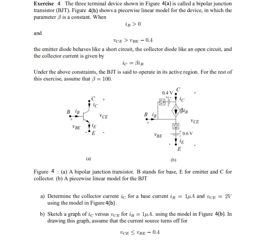
Exercise 4 The three terminal device shown in Figure 4(a) is called a bipolar junction transistor (BJT). Figure 4(b) shows a piecewise linear model for the device, in which the parameter 3 is a constant. When iB > 0 and UCEUBE -0.4 the emitter diode behaves like a short circuit, the collector diode like an open circuit, and the collector current is given by ic = BiB Under the above constraints, the BJT is said to operate in its active region. For the rest of this exercise, assume that 3 = 100. B iB VBE (a) iE E VCE B iB 0.4 V |||| VBE ic BiB E E VCE 0.6 V (b) Figure 4: (a) A bipolar junction transistor. B stands for base, E for emitter and C for collector. (b) A piecewise linear model for the BJT a) Determine the collector current ic for a base current i = 1μA and vCE = 2V using the model in Figure 4(b). b) Sketch a graph of ic versus UCE for ip = 1µA. using the model in Figure 4(b). In drawing this graph, assume that the current source turns off for UCE UBE-0.4
Exercise 4 The three terminal device shown in Figure 4(a) is called a bipolar junction transistor (BJT). Figure 4(b) shows a piecewise linear model for the device, in which the parameter 3 is a constant. When iB > 0 and UCEUBE -0.4 the emitter diode behaves like a short circuit, the collector diode like an open circuit, and the collector current is given by ic = BiB Under the above constraints, the BJT is said to operate in its active region. For the rest of this exercise, assume that 3 = 100. B iB VBE (a) iE E VCE B iB 0.4 V |||| VBE ic BiB E E VCE 0.6 V (b) Figure 4: (a) A bipolar junction transistor. B stands for base, E for emitter and C for collector. (b) A piecewise linear model for the BJT a) Determine the collector current ic for a base current i = 1μA and vCE = 2V using the model in Figure 4(b). b) Sketch a graph of ic versus UCE for ip = 1µA. using the model in Figure 4(b). In drawing this graph, assume that the current source turns off for UCE UBE-0.4

Related questions
Question
100%
Transcribed Image Text:Exercise 4 The three terminal device shown in Figure 4(a) is called a bipolar junction
transistor (BJT). Figure 4(b) shows a piecewise linear model for the device, in which the
parameter 3 is a constant. When
iB > 0
and
UCEUBE -0.4
the emitter diode behaves like a short circuit, the collector diode like an open circuit, and
the collector current is given by
ic = BiB
Under the above constraints, the BJT is said to operate in its active region. For the rest of
this exercise, assume that 3 = 100.
B iB
VBE
(a)
iE
E
+
VCE
BiB
0.4 V
VBE
BiB
VCE
+0.6 V
E
E
(b)
Figure 4: (a) A bipolar junction transistor. B stands for base, E for emitter and C for
collector. (b) A piecewise linear model for the BJT
a) Determine the collector current ic for a base current i = 1μA and vCE = 2V
using the model in Figure 4(b).
b) Sketch a graph of ic versus UCE for iB = 1μA. using the model in Figure 4(b). In
drawing this graph, assume that the current source turns off for
VCE
UBE- 0.4
Expert Solution
This question has been solved!
Explore an expertly crafted, step-by-step solution for a thorough understanding of key concepts.

This is a popular solution!

Trending now
This is a popular solution!

Step by step
Solved in 2 steps with 2 images
