Exercise 7 In the circuit of figure 1 below, the diode is characterized by its internal resistor rd and its threshold voltage Va. Express the output voltage Vs as a function of E. NA: ra = 50, V₁ = 0.7 V, R₁ = R₂ = 10k, R₁ = 1 k0, E = 12 V. Tis M Figure 1
Exercise 7 In the circuit of figure 1 below, the diode is characterized by its internal resistor rd and its threshold voltage Va. Express the output voltage Vs as a function of E. NA: ra = 50, V₁ = 0.7 V, R₁ = R₂ = 10k, R₁ = 1 k0, E = 12 V. Tis M Figure 1

Introductory Circuit Analysis (13th Edition)
13th Edition
ISBN:9780133923605
Author:Robert L. Boylestad
Publisher:Robert L. Boylestad
Chapter1: Introduction
Section: Chapter Questions
Problem 1P: Visit your local library (at school or home) and describe the extent to which it provides literature...

Related questions

Question
Exercise 7

Transcribed Image Text:Exercise 7
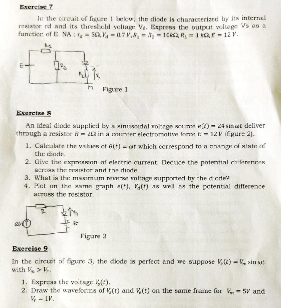
In the circuit of figure 1 below, the diode is characterized by its internal
resistor rd and its threshold voltage Va. Express the output voltage Vs as a
function of E. NA: ra= 50, V₁ = 0.7 V, R₁ = R₂ = 10k, R₁ = 1 kQ, E = 12 V.
M
2013
M
Exercise 8
An ideal diode supplied by a sinusoidal voltage source e(t) = 24 sin wt deliver
through a resistor R = 202 in a counter electromotive force E = 12 V (figure 2).
Figure 1
1. Calculate the values of 0(t) = wt which correspond to a change of state of
the diode.
2. Give the expression of electric current. Deduce the potential differences
across the resistor and the diode.
R
3. What is the maximum reverse voltage supported by the diode?
4. Plot on the same graph e(t), Va(t) as well as the potential difference
across the resistor.
ZYD
E
Figure 2
Exercise 9
In the circuit of figure 3, the diode is perfect and we suppose Ve(t) = Vm sin wt
with Vm > Vr.
1. Express the voltage V₂(t).
2. Draw the waveforms of V, (t) and Ve(t) on the same frame for Vm = 5V and
V₁ = 1V.
Transcribed Image Text:Exercise 7
In the circuit of figure 1 below, the diode is characterized by its internal
resistor rd and its threshold voltage Va. Express the output voltage Vs as a
function of E. NA: ra= 50, V₁ = 0.7 V, R₁ = R₂ = 10k, R₁ = 1 kQ, E = 12 V.
M
2013
M
Exercise 8
An ideal diode supplied by a sinusoidal voltage source e(t) = 24 sin wt deliver
through a resistor R = 202 in a counter electromotive force E = 12 V (figure 2).
Figure 1
1. Calculate the values of 0(t) = wt which correspond to a change of state of
the diode.
2. Give the expression of electric current. Deduce the potential differences
across the resistor and the diode.
R
3. What is the maximum reverse voltage supported by the diode?
4. Plot on the same graph e(t), Va(t) as well as the potential difference
across the resistor.
ZYD
E
Figure 2
Exercise 9
In the circuit of figure 3, the diode is perfect and we suppose Ve(t) = Vm sin wt
with Vm > Vr.
1. Express the voltage V₂(t).
2. Draw the waveforms of V, (t) and Ve(t) on the same frame for Vm = 5V and
V₁ = 1V.
Expert Solution
This question has been solved!
Explore an expertly crafted, step-by-step solution for a thorough understanding of key concepts.

Step by step
Solved in 4 steps with 3 images

Knowledge Booster


Learn more about
Need a deep-dive on the concept behind this application? Look no further. Learn more about this topic, electrical-engineering and related others by exploring similar questions and additional content below.Recommended textbooks for you
Introductory Circuit Analysis (13th Edition)
Electrical Engineering
ISBN:
9780133923605
Author:
Robert L. Boylestad
Publisher:
PEARSON

Delmar's Standard Textbook Of Electricity
Electrical Engineering
ISBN:
9781337900348
Author:
Stephen L. Herman
Publisher:
Cengage Learning

Programmable Logic Controllers
Electrical Engineering
ISBN:
9780073373843
Author:
Frank D. Petruzella
Publisher:
McGraw-Hill Education
Introductory Circuit Analysis (13th Edition)
Electrical Engineering
ISBN:
9780133923605
Author:
Robert L. Boylestad
Publisher:
PEARSON
Delmar's Standard Textbook Of Electricity
Electrical Engineering
ISBN:
9781337900348
Author:
Stephen L. Herman
Publisher:
Cengage Learning
Programmable Logic Controllers
Electrical Engineering
ISBN:
9780073373843
Author:
Frank D. Petruzella
Publisher:
McGraw-Hill Education

Fundamentals of Electric Circuits
Electrical Engineering
ISBN:
9780078028229
Author:
Charles K Alexander, Matthew Sadiku
Publisher:
McGraw-Hill Education

Electric Circuits. (11th Edition)
Electrical Engineering
ISBN:
9780134746968
Author:
James W. Nilsson, Susan Riedel
Publisher:
PEARSON

Engineering Electromagnetics
Electrical Engineering
ISBN:
9780078028151
Author:
Hayt, William H. (william Hart), Jr, BUCK, John A.
Publisher:
Mcgraw-hill Education,