Explain how you think the model would look like if a transistor is in velocity saturation region?
Q: In a transistor circuit, collector load is 4 kΩ whereas quiescent current (zero signal collector…
A: Given, Collector load, Rc = 4 kohm Quiescent current (IcQ)= 1 mA
Q: Explain how a common collector transistor configuration should be describe. Mention the terminals…
A: n the case of common collector configuration the collector is common whereas the input is base and…
Q: 1. Write the procedures in finding the pins and state the type of the transistor tor PNP and NPN…
A: to write the procedures in finding the pins and state the type of the transistor for PNP and NPN…
Q: Refer to the figure shown, the collector-base voltage of the transistor if β = 140 is?
A: Given here a electrical circuit and asked to find the collector base voltage.
Q: Determine IB, Ic, VCE and draw the load line. State whether the transistor is biased in cutoff,…
A:
Q: the diagram shown is a block diagram for a qpsk modulator circuit draw a circuit diagram for it
A: Circuit diagram :
Q: Explain the transistor operation using a NPN Type Resistor.
A: According to the question, we have to explain NPN Type Resistor.
Q: Explain the process of thermal runaway for transistors
A: For a bipolar junction transistor, the collector current can be expressed as IC=βIB+1+βICO--->(1)…
Q: How we can make sure that the transistor work in ON state or OFFstate?How we can make sure that the…
A:
Q: 2- Illustrate the following: A. Define Biasing ?I B. Write the three types of biasing circuit in…
A: A good question on transistor biasing . Have a look below:-
Q: What is a transistor and what it’s used for ?
A:
Q: 4- Explain the working principle of pnp transistor showing all necessary figures.
A: We are authorized to answer one question at a time, since you have not mentioned which question you…
Q: a)what is transistor? Analyze the (V-I) characteristic curve of NPN transistor. b)Also explain why…
A:
Q: How do you draw the small signal equivalent circuit for common source, common gate and common drain…
A: We need to draw small signal model of different amplifier .
Q: What is Quiescent? What does it mean a transistor in saturation?
A: Quiescent point: The constant Dc voltage or current at a certain terminal of an active device, such…
Q: hat are the conditions for biasing the transistors properly?
A: Solution:- Step 1:- The requirement of a biasing circuit:- 1.Establishment of the operating point in…
Q: Figure shows the open circuit failures in a transistor. What will be the circuit behaviour in each…
A: The explanation for all the three cases are as follows.
Q: Describe what the load line is and what is it for?
A: Q-point- Q-point is the intersection point of the DC-load line and forward characteristic. If few…
Q: How the transistor can be used as an amplifier in CE configuration?
A: Thyristor comprises of three terminals, Base, Emitter and collector. in the CE ( common emitter)…
Q: Below diagram shows the voltage divider bias method .Draw the dc load line and determine the…
A:
Q: (1) The transistor shown in the circuit of Figure 1 can be operated either as a linear regylator or…
A: (1). As a linear regulator - If a transistor is operated as a linear regulator, then the transistor…
Q: d) What is the difference between npn and pnp transistor?
A: We are authorized to answer one question at a time, since you have not mentioned which question you…
Q: For an npn transistor, dc collector current is 4.55 mA and the dc base current is 12 uA. If the dc…
A: For an npn transistor, the relation between the dc collector current IC and the dc base current IB…
Q: Fixed-bias Configuration a. What happen to the collector voltage, if the collector resistor is…
A:
Q: What can you say about the voltage gain of an emitter follower? The current gain? The power gain?
A: The common collector junction transistor amplifier is commonly called an emitter follower. The…
Q: Sketch the DC load line for the fixed bias circuit for each transistor case and place the Q-point on…
A:
Q: Ideally. for linear operation a transistor should be biased so that the Q-point is halfway between…
A:
Q: how is this an nmos transistor? what region is this diagram better to operate in voltage amplifier?
A: Given transistor circuit is - Given transistor has positive gate to source voltage VGS.
Q: Determine the operating point of the transistor in the circuit given in the figure and draw the load…
A: The circuit is as shown below :
Q: Explain DC load line and Q point for any transistor configuration.also state the necessity of…
A: To Explain DC load line and Q point for any transistor configuration.To state the necessity of…
Q: RC Ge L Si
A:
Q: Q6. a) What is a transistor? b) Describe the action of npn transistor in detail. c) Name the…
A: Given a.In this question we are interested in the the definition of transistor. b.And working of…
Q: Determine the: a) dc transistor terminal voltages b) h?? c) Rin’ d) Load voltage, ?? e)…
A: As per company guidelines we can solve only first three sub parts kindly post another parts…
Q: (A) WHAT ARE THE THREE PHASES Of TRANSISTOR CIRCUIT ANALYSIS? (B) WHAT ARE THE STEPS IN THE THIRD…
A: A) The three phases of transistor circuit analysis are as follows, DC analysis Calculation of…
Q: What is biasing circuit in a small signal equivalent circuit?
A:
Q: Discuss transistor loadline and operating point
A: Transistor Load line: In the graphical analysis of offline power circuits, the line load line is…
Q: What is scientific Reason?d. Briefly explain how a Transistor can be used as a Switch and as an…
A: Scientific reasoning (SR):- scientific reasoning is a process of solving problems, which included a…
Q: a) How is the input characteristic of a common emitter BJT transistor measured? Input characteristic…
A: BJT TRANSISTOR The Bipolar Junction Transistor is a semiconductor device which can be used for…
Q: Explain NPN transistor working principle
A: Bipolar junction transistors (also known as BJTs) are charge-carrying transistors that use both…
Q: Explain how a transistor can be used as a switch and also as an amplifier?
A: The explanation is as follows.
Q: How many noise sources does each transistor have?
A: Transistor A Transistor is basically a semiconductor device that is used to amplify or switch…
Q: (b) Label the Base, Collector and Emitter in the following figure. What type of transistor is this,…
A: We need to tell name of bjt terminal and type of bjt .
Q: the circuit given in Figure,determine the operating point of the transistor and draw the load line.
A: In this question , we will find operating point of transistor...And sketch dc load line..
Q: Q1: for a silicon transistor in the figure below = 200 dc {What is the voltage between the collector…
A: The Q point is defined by IC and VCE. The base current can be calculated as: So, the collector…
Q: a) What is a Field effect transistor? Give its description and classification. b) Explain the…
A: The detailed answer is solved below according to the given parameters and instructions in the…
Q: b. Explain why the BC junction of an NPN transistor is reversed biased?
A:
the slide is shown below. Explain how you think the model would look like if a transistor is in velocity saturation region?
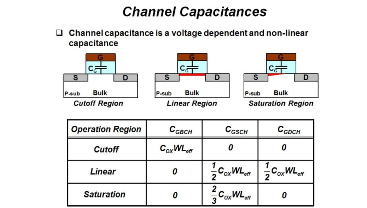
Step by step
Solved in 2 steps
- 41. Draw a circuit diagram for a series circuit containing a R = 0.4 k resistance, a coil with L = 0.4 H inductance, and a C = 20- F capacitor connected across a 140-V, 60 Hz voltage source. What should be the current (I) through the supply voltage and the phase angle between current and the source?9. What will be the impedance of a LR-C circuit if it has a circuit current of 3A and a supply voltage of 120V? A. 45ohm B. 50 ohm C. 40 ohm D. 35 ohm 10. A pure inductance of 100mH is connected in parallel to a 25microfarad capacitor. The network is connected to a 200V, 60Hz supply. Determine the circuits current. A. 2A B. 3.42A C. 4A D. 10AThe circuit below has values: VT = 120 Vac, f = 24.595 kHz, L1 = 130 mH, L2 = 132 mH, and L3 = 214 mH. Determine inductive reactances XL1, XL2, and XL3 and the value of series inductive reactance XLT . Calculate the current I in the circuit. Determine the voltages across L1, L2, and L3 in the circuit. Calculate the total inductance LT in the circuit.
- Calculate the required DC supply voltage VCC when RC=1813 ohms, IB=33 uA, VC=6V, R2=5425 ohms, RE=338 ohms and B=148.1.Enumerate five formulas for four series connected capacitances across Vt source and draw the circuit. 1. Enumerate five formulas for four parallel connected capacitances across Vt source and draw the circuit.A 250-V circuit, consisting of a resistor, an inductor and a capacitor in series, resonates at 50 Hz. Thecurrent is then 1A and the p.d. across the capacitor is 500 V. Calculate (i) the resistance (ii) theinductance and (iii) the capacitance Answer:
- a) If the operating frequency increases in Figure below, the current_____and phase angle______ ?A) Increases, decreasesB) Increases, increasesC) Decreases, decreases.D)Decreases, increases.b) Calculate the voltage drop across the capacitor in Figure below.A) 14.4 VC) 3.69 VB) 11.5 VD) 4.82 VA series circuit contains a 20 ohm resistor anda inductor with an inductance of 0.093H if the circuit has a fequencey of 60Hz what is the inductive reactance Xl and total impedance Z of the circuit?Calculate the voltage Va by node analysis, please show the procedure step by step.
- a capacitor C is connected in parallel to a resistor R across a 100V, 100Hz supply. The supply current is 10A at a phase angle of 64.45 degree. Determine the value of R and C. A. 25.52 ohm, 130.51 microfarad B. 5 ohm, 10microfarad C. 1kohm, 2 F D. 10 ohm, 25 micro FaradIn a balanced network, AB is a resistance of 500Ω in series with an inductor of 0.18 H, BC and DA are non inductive resistance of 1000Ω each and CD consists of a resistance R in series with capacitor C. A potential difference of 5 V at a frequency of 5000/2π is applied between points A and C. Determine the value of R and C.A noninductive load with a resistance of 30 Ω is connected in series with a capacitor. The capacitor has a capacitive reactance of 25 Ω and negligible resistance. The series circuit is energized from a 210 V, 60 Hz source. Determine: the impedance of the series circuit. the current, in amperes. the loss in volts across the noninductive resistance load. the loss in volts across the capacitor.