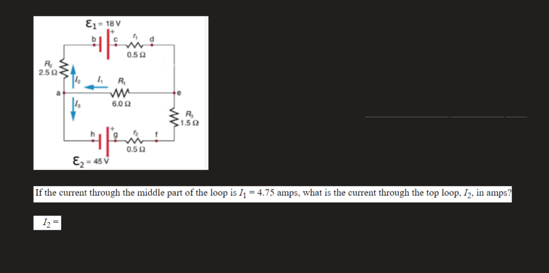
Ez= 18 V 0.5 Q R 2.5N< 1, R, a 6.0 Ω R 1.52 12 0.5 N E2 = 45 V %3D If the current through the middle part of the loop is Ij = 4.75 amps, what is the current through the top loop, I,, in amps? I, =


Q: Q1 Consider the following circuit +15 V Rc 1.5 kN R 20 kN Bpc = 150 B R2 4 kn RE 680 N 1- Determine…
A: 1) Assume Q is in active VTh=15×44+20=2.5 VVTh=3.33 k× IB+0.7+IE×6802.5-0.7=3.33k…
Q: Thevenin and Norton Equivalent: 15). For the circuit in Fig. 4.109, find Thevenin equivalent between…
A: We need to find out thevenin equivalent circuit and norton equivalent circuit
Q: R1=120 ka, Re2=60 kn, C,=C,=C3=C;=1 µF, B=140, h=1.2 ko, Re=1 k0, R.=4 kQ, R =2 kN, R=1 kQ ve V = 12…
A:
Q: o 20 V 2.2 kΩ 390 k2 B= 140 = 100 k2 1.2 kΩ
A: First of all, the dc analysis of the amplifier should be done as below. Write the KVL expression in…
Q: Determine the Norton equivalent of the given circuit as seen by terminals a and b. (There should be…
A:
Q: From the circuit below, calculate the AC quantity r: Vcc = 24 V R = 36 k2 Rc = 1.8 k2 Cout B = 150…
A:
Q: In experiment 4, the tabulation of the open circuit test is given below: V, in Volts Vo in Volts K…
A:
Q: The presence of a current source anywhere in a circuit result in a super mesh Select one: O a. True…
A: SUPER MESH: When two meshes share a common current source (dependent or independent) then a super…
Q: Q 4: Find the Thevenin and Norton equivalent circuits for the circuit shown in Fig.4 5 0 jll Q wwH…
A: In this question, we need to draw the Thevenin equivalent circuit and Norton equivalent circuit.
Q: For the circuit in Figure 4, 22 V 5.6 kN 330 kN V. Cc ß = 90 Vị CB r, = 40 kN 1.2 kN 0.47 kN CE…
A: Approximate T-model- T-model is also known as common base model, and resistance model. i)re- It is…
Q: 10 22 0.5Q 10Ω 20 Q 10V ЗА 2A 15V Source Source Sink Source 30 12
A:
Q: Q/ For the network of Figure below, calculate A, using r, model. o 22.7 V Rc = 1.3 KN %3D RB = 1275…
A: Given : Beta = 149 In the question they have given common emitter amplifier & they want to…
Q: In the circuit shown below, if R=2.7, find the loop current 1j (in A) 1 A 12 V 4Ω) 5Ω 2 A
A: 
Q: H.W. 2.18: If Req = 50 N in the circuit in Figure below, find R. Solution:R= 106 2 10 2 R 30 2 Reg…
A:
Q: x [n] yous Consider the following system ー2 D Assuming the condition that a 2 /2, what are all the…
A:
Q: H.W. 2.18: If Req 50 Q in the circuit in Figure below, find R. Solution:R= 106 2 10 2 30 2 Reg 12 2…
A:
Q: The equivalent resistance RAB in the above circuit 100 2 A 100 2 100 2 Select one: O a. 150 S2 Q b.…
A:
Q: 2. Find the equivalent resistance Rab in the circuits of Figure below. a o 102 60 2 30 Ω bo 20 2
A: If two resistors are connected in series then its equivalent resistance is sum of the individual…
Q: Consider the following circuit : Vcc RC R1 Cc R2 RE You are required to determine IBo using the…
A:
Q: 3) Determine the total current I in the given circuit. 20 Q mn wwww 10 12. 15 V 250 www 2.50 10 Q2…
A: Below find the answer !!
Q: 6 A 10 40 V 60 50 20 V. 1 10 A Figure Ql(a) (a) For the circuit shown in Figure QI(a), explain…
A:
Q: Determine the value of the Current I3. +1 12 V + - www 852 O A. 0.44 Amps OB. 1.05 Amps OC. 0.15…
A: We need to find out the current for given circuit
Q: Find the Thevenin and Norton equivalent circuits for the circuit shown in Fig.4 5 Q jll N H 2Ω ww…
A: In this question, Find the Thevenin equivalent and Norton equivalent circuit acorss the terminal a…
Q: II. A-to-Y Conversion A. Solve for the required values with complete solution and progressive…
A:
Q: 5.2 For the circuit of Fig. 5.7, use superposition to obtain the voltage across each current source.…
A: Note:a) A voltage source (in operative) is short circuited (or) replaced by its internal resistance.…
Q: Find the output voltage v, (t) for the circuit shown in Figure 1. 6 H ll + 2H v(1)= 24cos(41+140°)…
A: Observe the given dot polarity, from one dot current isentering and from other dot current is…
Q: Q.41: The following DC measurements were made on the resistive network: Measurement 1 V=1mV 4=0A…
A: According to question: Using measurement 1 data and measurement 2 data the 'Z' parameters of the…
Q: In the given circuit, /ỵ = 0.0004v1 A. a 10 k2 20 k2 I bo With respect to the given circuit,…
A:
Q: 20 Find the current through the 40 resistor of the circuit in ww Ans : ITOTAL= 0.707 Amp 40 50 V 10…
A:
Q: 12 4Ω 6Ω a I1 2Ω RL V1 For the circuit shown above, find the Norton current as seen from the a-b…
A: In this question we will find Norton current from load terminals....
Q: d V, using Mesh Analysis. ... 4 mA 2 kN (1) 2 mA 1 kN 1 kN 1 k 1 mA C2 kN
A: Use mess equation for mesh not containing any current source
Q: For the circuit shown, what is the Norton equivalent resistance, RN? 4 V 40 5 A(1 4Ω 40 O 1.33 N O…
A: We will find equivalent resistance between a and b to calculate norton resistance.
Q: 2. Determine the values of vi, v2, is, v4, vs, and is. 50 50 15 0 V4 + 12 V 40 2 tis 10 0 20 v2 + d…
A:
Q: Q/ For the network of Figure below, calculate A, using re model. o 22.7 V Rc = 1.3 KQ Rв 3 450 KD…
A:
Q: 95A R2 154,3 SOURCE Rt ci =1.70 AMe Ez=/,70 Amp THE SOURCE THE Type Of WitICH s Not Speci FIED,…
A:
Q: Solve the approximate value of VE of Figure 46. VCc R1 $2.7ka V= 10.6V %3D 20uA Q1 Beta = 100 V, VE…
A:
Q: In the circuit given below, R= 30 Q. Find vo and lo 50 2 10 Q2 www ww % 250 V io 10Ω 0.2% + The…
A: The circuit diagram is shown below, Where,R=30 Ω
Q: The circuit shown below on the left has the following parameters: Vs = 11 V Is=7A R₁ = 1.20 R₂=2.20…
A:
Q: R, V1 = 3,0 V, V2 = 4,5 V y V3 = 5,0 V I, R V R1 = 1,00, R2 = 4,0 Q y R3 = 3,0 0. a) Vab = Va - Vb.…
A:
Q: Determine the Norton equivalent of the given circuit as seen by terminals a and b. (There should be…
A: The solution is given below
Q: Consider the circuit shown in the figure below, the circuit parameters are as given below; 13 = 4 mA…
A: Right Answer option D. 6 mA
Q: Given the circuit in Fig. 2.101 and that the resis- tance, Reg, looking into the circuit from the…
A: The solution is given below
Q: For the circuit below, and assuming Vf=0.5 V, fınd labeled current I and voltage V. + 3 V 6 kN IZ D,…
A:
Q: Determine the Norton equivalent of the given circuit as seen by terminals a and b. (There should be…
A: In this question, Draw the Norton equivalent circuit across the terminal a and b. If resistance…
Q: Also show that the power balance is achieved.
A: Mark the node by their voltages as shown below-
Q: (a) Find the Norton's equivalent circuit external to points a and b for the network shown in Figure…
A: Here for Norton's equilent first remove load resistor RL and For Norton's current shor the…
Q: For the network of Figure Q4 (b), Find vc, Vs, ik and for t>0. Let vc (0) = 30 v. (b) 162 10Ω 0.2F…
A:
Q: :) For the circuit shown, unCox = 4 µpCox = 400 µA/V², and |Vt = 0.4 V, 1 = 0, L= 0.2 %3D um and W =…
A: The drain current is equal for both MOSFETs
Q: A PV system uses 720 silicon PV cells connected in an array which supplies up to 120 V. .How many PV…
A: Given, A PV system uses N=720 silicon PV cells. Total supplied voltage, Vs=120 V One cell delivers,…


Trending now
This is a popular solution!

Step by step
Solved in 2 steps with 2 images

- According to the circuit given in the figure, VT=25mV, |VBE|=0.7V, R1=1487.51Kohm, R2= 7.42Kohm, R3= 6.71Kohm , R4= 2.87Kohm, VCC= 13.00V, VEE= 1.00V , VA=28.21V , Beta= 120.00 , Rs= 36.18ohm, Ry= 15.61Kohm Calculate the IC current, Ri, R0 and voltage gain(V0/V1) according to the source by performing a complete analysis. When performing your operations, 2 steps will be taken after the point. choose the closest one from the stylish ones according to the +/-10% margin of error. There is only 1 correct answer to the question.In the circuit given in the figure VT = 25mV, | VBE | = 0.7V, R1 = 515.22Kohm, R2 = 10.89Kohm, R3 = 2.41Kohm, R4 = 1.03Kohm, VCC = 12.00V, VEE = 2.00V, VA = 12.51V, Beta Since = 107.00, Rs = 23.19ohm, Ry = 8.18Kohm, calculate the IC current, Ri, R0 and voltage gain according to the Source (V0 / V1) by making full analysis.In the circuit given in the figure, VT = 25mV, | VBE | = 0.7V, R1 = 1519.62Kohm, R2 = 48.01Kohm, R3 = 3.22Kohm, R4 = 1.38Kohm, VCC = 13.00V, VEE = -6.00V, VA = 19.82V, Since Beta = 163.00, Rs = 23.65 ohm, Ry = 18.08Kohm, by Source calculate IC current, Ri, R0 and voltage gain (V0 / V1) with full analysis.
- In the circuit given in the figure, VT = 25mV, | VBE | = 0.7V, R1 = 1402.66Kohm, R2 = 32.67Kohm, R3 = 2.91Kohm, R4 = 1.25Kohm, VCC = 10.00V, VEE = -5.00V, VA = 25.00V, Since Beta = 208.00, Rs = 28.63ohm, Ry = 13.62Kohm, calculate the IC current, Ri, R0 and the voltage gain according to the Source (V0 / V1) by full analysis.In the circuit given in the figure VT = 25mV, | VBE | = 0.7V, R1 = 712.91Kohm, R2 = 43.27Kohm, R3 = 2.29Kohm, R4 = 0.98Kohm, VCC = 10.00V, VEE = -4.00V, VA = 10.06V, Beta = 137.00, Rs = 38.43ohm, Ry Calculate the IC current according to = 16.55Kohm, Ri, R0 and the voltage gain (V0 / V1) according to the Source by full analysis When making your transactions, 2 steps will be taken after the point. Select the closest option according to +/- 10% margin of error. There is only one correct answer to the question.Subject : ELECTRONIC CIRCUIT ANALYSIS AND DEVICES Please give the DC ANALYSIS CIRCUIT and AC EQUIVALENT CIRCUIT of this problem before proceeding to find letter c. (Note : Neglect Vbe)
- Q1) Conduct an evaluation on the practical applications of the concepts of electromagnetism and submit a written report which includes the following. a) Design a circuit which utilizes the concept of electromagnetism and submit a simulation circuit for the same (use simulation tool of your choice) b) Write down the selected values of the components used for example the values of resistors, transistor used, capacitors etc c) Obtain the output for the ciruit using any sinks like CRO, loud speakers etc. d) Discuss about the principles of electromagnetism used in the simulation I WANT QUESTION (D)Subject : ELECTRONIC CIRCUIT ANALYSIS AND DEVICES Please give the DC ANALYSIS circuit and AC EQUIVALENT CIRCUIT of this problem before proceeding to find letters a, and b. (Note : Neglect Vbe)Explain the difference between cumulative- and differential-compounded connections.
- It is known that Vi = 62 mV IDSS = 12 mA, VP = -4 V, VGSQ = -2.5 V, RD = 3.2 kΩ and RS = 1.2 kΩ in the circuit in the figure. Accordingly, what is the value of the output voltage of the circuit (V0)? NOTE: The FET output impedance (rd) will not be taken into account in the calculations.Power Electronics. In the Buck-Boost DC-DC converter circuit:Welding voltage [40-80]VSwitching frequency (f) 25khzVoltage between load terminals 55VCapacitance value 470uFLoad current value [10-25]A Under these conditions, which is the lowest ripple (delta IL) amount of the current passing through the coil (L) in Amps for the lowest L inductance value that can keep the DC-DC converter in a continuous current state? A) 23.9803B) 118.75C) 84.3750D) 47.5E) 59.9507F) 33.75In the circuit given in the figure VT = 25mV, | VBE | = 0.7V, R1 = 950.31Kohm, R2 = 22.50Kohm, R3 = 2.51Kohm, R4 = 1.08Kohm, VCC = 13.00V, VEE = 3.00V, VA = 13.08V, Beta Since = 193.00, Rs = 22.94ohm, Ry = 14.49Kohm, calculate the IC current, Ri, R0 and the voltage gain according to the Source (V0 / V1) by making full analysis. When making your transactions, 2 steps will be taken after the point. Select the closest option according to +/- 10% margin of error. There is only one correct answer to the question.