F. Use a suitable value for RG Rp = 1 K2 Rs = 250 2 . 8x10 For the given circuit What would it look like using an oscilloscope to Measure the V-in and th V-out What would the traces of each look like What is the measured value of Av?
F. Use a suitable value for RG Rp = 1 K2 Rs = 250 2 . 8x10 For the given circuit What would it look like using an oscilloscope to Measure the V-in and th V-out What would the traces of each look like What is the measured value of Av?

Electricity for Refrigeration, Heating, and Air Conditioning (MindTap Course List)
10th Edition
ISBN:9781337399128
Author:Russell E. Smith
Publisher:Russell E. Smith
Chapter8: Basic Electric Motors
Section: Chapter Questions
Problem 22RQ: What is the unit of measurement for the strength of a...

Related questions
Question
100%
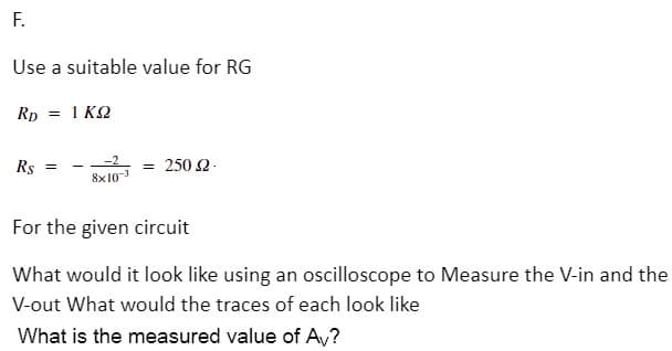
Transcribed Image Text:F.
Use a suitable value for RG
Rp = 1 KQ
Rs =
= 250 2.
8x10³
For the given circuit
What would it look like using an oscilloscope to Measure the V-in and the
V-out What would the traces of each look like
What is the measured value of A,?
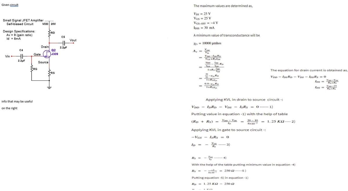
Transcribed Image Text:Given circuit
The maximum values are determined as,
Vps = 25 V
VGs = 25 V
VGS-OFF = -4 V
Small Signal JFET Amplifier
Self-biased Circuit
VDD 20V
Ipss = 30 mA
Design Specifications:
Av = 9 (gain ratio)
Id = 8mA
3RD
A minimum value of transconductance will be
C5
Vout
8s = 10000 umhos
Drain
Q2
J309
2.2µF
C4
V
A,
=
Gate
Vin
2.2µF
Source
Ins Ro
SRG
The equation for drain current is obtained as,
ERS
20
VDp - IpsRp – Vps - IpsRs = 0
Voo-Vrs
Ips = Rok,
0.8-RD
Ips = V 5
Applying KVL in drain to source circuit -:
info that may be useful
on the right
VDD - IDRD – Vps - IşRs = 0------ 1)
Putting value in equation -1) with the help of table
(Rp + Rs) =
Vrn - Vos
20 – 10 = .25 K2 ---- 2)
Applying KVL in gate to source circuit -:
-VGs - 1sRs = 0
Ip =
3)
Rs =
4)
With the help of the table putting minimum value in equation -4)
Rs -
- - 250 2----5)
Putting equation -5) in equation -1)
Rp = 1.25 KN – 2502
Expert Solution
This question has been solved!
Explore an expertly crafted, step-by-step solution for a thorough understanding of key concepts.

Step by step
Solved in 4 steps with 4 images

Knowledge Booster


Learn more about
Need a deep-dive on the concept behind this application? Look no further. Learn more about this topic, electrical-engineering and related others by exploring similar questions and additional content below.Recommended textbooks for you
Electricity for Refrigeration, Heating, and Air C…
Mechanical Engineering
ISBN:
9781337399128
Author:
Russell E. Smith
Publisher:
Cengage Learning
Electricity for Refrigeration, Heating, and Air C…
Mechanical Engineering
ISBN:
9781337399128
Author:
Russell E. Smith
Publisher:
Cengage Learning