F1. The rigid bar ABC in the figure is supported by a clevis and pin at its right hand side and by two cables AD and BE fastened at the positions shown along the length of the bar. The cables are fabricated from steel and are 1.50 in. in diameter. Determine the stresses in the cables and their displacements. E 6 ft 45° 3 ft B 3 ft F = 80 kip 6 ft 6 ft
F1. The rigid bar ABC in the figure is supported by a clevis and pin at its right hand side and by two cables AD and BE fastened at the positions shown along the length of the bar. The cables are fabricated from steel and are 1.50 in. in diameter. Determine the stresses in the cables and their displacements. E 6 ft 45° 3 ft B 3 ft F = 80 kip 6 ft 6 ft

Mechanics of Materials (MindTap Course List)
9th Edition
ISBN:9781337093347
Author:Barry J. Goodno, James M. Gere
Publisher:Barry J. Goodno, James M. Gere
Chapter2: Axially Loaded Members
Section: Chapter Questions
Problem 2.10.2P: The flat bars shown in parts a and b of the figure are subjected to tensile forces P = 2.5 kN. Each...

Related questions

Question
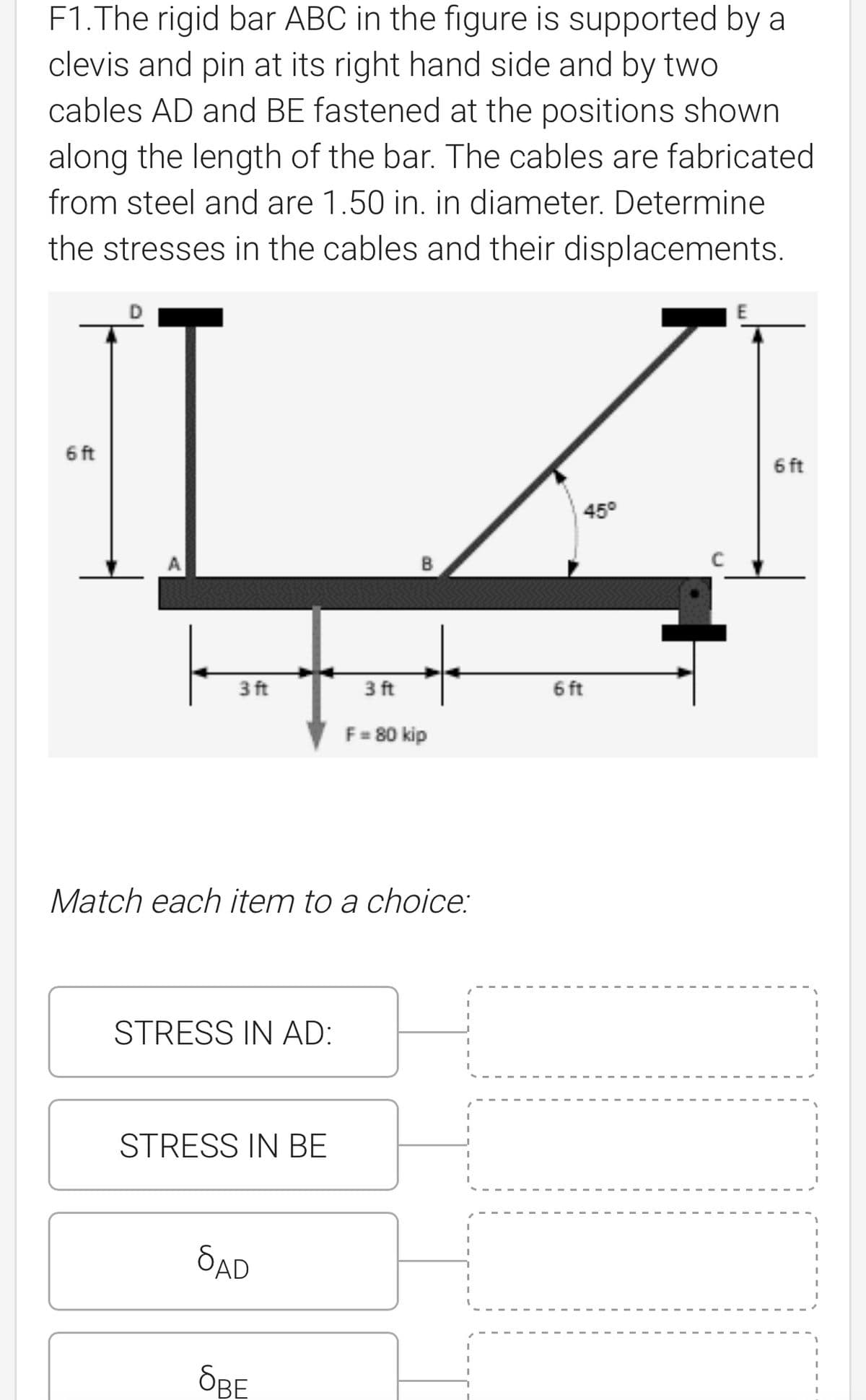
Transcribed Image Text:F1. The rigid bar ABC in the figure is supported by a
clevis and pin at its right hand side and by two
cables AD and BE fastened at the positions shown
along the length of the bar. The cables are fabricated
from steel and are 1.50 in. in diameter. Determine
the stresses in the cables and their displacements.
6 ft
6 ft
45°
3 ft
3 ft
F = 80 kip
Match each item to a choice:
STRESS IN AD:
STRESS IN BE
SAD
OBE
6 ft
Expert Solution
This question has been solved!
Explore an expertly crafted, step-by-step solution for a thorough understanding of key concepts.

Step by step
Solved in 3 steps with 2 images

Knowledge Booster


Learn more about
Need a deep-dive on the concept behind this application? Look no further. Learn more about this topic, mechanical-engineering and related others by exploring similar questions and additional content below.Recommended textbooks for you
Mechanics of Materials (MindTap Course List)
Mechanical Engineering
ISBN:
9781337093347
Author:
Barry J. Goodno, James M. Gere
Publisher:
Cengage Learning
Mechanics of Materials (MindTap Course List)
Mechanical Engineering
ISBN:
9781337093347
Author:
Barry J. Goodno, James M. Gere
Publisher:
Cengage Learning