Figure P2.2 5 mA 18 V Figure P2.2 Full Alternative Text
Q: In the figure is shown a battery having an emf of 12 Volts and an internal resistance of 0.40 Ohm. A…
A: In the circuit, Find the value of R for Maximum power transfer to the load R. Current and power in…
Q: Explain the concept of power absorbed and power supplied by circuit elements if passive sign…
A:
Q: Q2 (a) For the circuit shown in Figure Q2(a), la 5 mA 10 k2 Vo 5 k2 20 k2 Ix = 0.01V0 Figure Q2(a)…
A:
Q: Q2. A meeting hall in an organization is to be provided with a lighting installation. The hall is 30…
A: As per the guidelines, we need to solve only first three sub parts
Q: For the circuit shown in Figure. Calculate the Total "I" Current in the Circuit when R1=14 Ohms,…
A: if two resistors R1 and R2 are connected in parallel than equivalent resistance is R1 + R2 . if two…
Q: Circuit connection for minimum current delivered by a 30V DC source: Parallel Assigned resistance…
A: Note: As per Bartleby guidelines, we are supposed to provide solution of first question only , I…
Q: Exercise 2-1 a) Find the currents I1, I2, and Iz in the circuit shown in Figure. b) Find the…
A:
Q: If you are to connect a variable resistor accros terminal ab and adjust it for maximum power…
A: For maximum power transfer theorem maximum power is delivered to load when load resistance is equal…
Q: AO 332 142 432 20Ω
A:
Q: IS required to maintain a loading of 5 kW in a heating unit. At an initial temperature of 15 C°, a…
A: Given that Tin =Tref=15.cV =220 vVref=200 v∞ =0.0006;we have to ccalculate the final temperature…
Q: 4) In a voltage source: a) Current flow from -ve terminal to +ve terminal inside the battery b)…
A:
Q: 2- Consider the following circuit. Suppose R1 = R2 = 200 Ohm and the battery is 50 V. Calculate the…
A: When the same current flows through all they resistors, they are said to be in series. In series…
Q: Below, a simple electric circuit scheme is given. Vs = 10 V. Ammeter R1 R3 ww. ww. Ra Ro R2 Rv R4 Vs…
A: Given R1=5000ΩR2=4000ΩR3=7000ΩR4=8000Ω
Q: R b a V1 V2 V3 V4 V5 Ideal voltmeters are set to read five effective values and connected as shown.…
A:
Q: 1) For the network shown in the below figure, the value of current needs to be measured in the 10002…
A:
Q: In this network, the current source value is Is = 30 mA, while the resistances are R₁ = 100 2 and R₂…
A: Given, The network is Is=30 mAR1=100 ΩR2=550 Ω
Q: Figure Q1(a) shows an external circuit, with a resistance of 2 Q, connected across the terminals A…
A:
Q: (5) A manufacturing plant installed the system above (500 KW) and has a full load capacity of 700KW…
A: Note: Here it is mentioned that "the system above". but the system details not given. We assume,…
Q: Q2- volage=120V. The days of autonomy=12 day. The total daily load=34AH/day. For PV /Battery…
A: Different energy sources are required in day to day life. These energy sources can be renewable or…
Q: In the figure is shown a battery having an emf of 12 Volts and an internal resistance of 0.40 Õhm. A…
A: We are authorized to answer one question at a time, since you have not mentioned which question you…
Q: Required information No currents flow in the circuit diagrammed before the switch is closed.…
A:
Q: Consider the following circuit: 502 V1 V2 2A 1002 50Ω 102 50V 1002 1002 30V 100Ω 2002 1A (a) Find…
A: NOTE : AS PER GUIDELINES OF BARTLEBY ***For a multiple sub parts question , I supposed do only first…
Q: Suppose you want to add a third radiator to your garage that is identical to the two radiators you…
A: Since the radiators are identical, let the resistance of each radiator be R. The equivalent…
Q: 2.10 The current is in the circuit shown is 2 A. Calculate a) v b) the power absorbed by the…
A: Hello. Since your question has multiple sub-parts, we will solve the first three sub-parts for you.…
Q: Design a 24v zener regulated power supply circuit that will power a 500 ohms load with 1A of of…
A: Mode of operation of zener diode Forward biased mode ( behave like on switch) Reverse biased mode(…
Q: 19. Consider the circuit present on the right. Assume all emfs are ideal batteries. B a) What is the…
A: The given circuit diagram is shown below:
Q: What price would you have to get for the electricity you produce to obtain a 10% return on the plant…
A: As per Bartleby guidelines I can give solution for the first question only as second part is having…
Q: NOTE: Answers should be handwritten and precise. • Draw diagrams to support your answers • Refer to…
A:
Q: Using the circuit of the Figure, find the voltagethat the meter reads if VS = 24 V and RS has…
A: Write the expression for the voltmeter voltage.
Q: A 2-wire d.c. distributor AB, 1000 m long has a total resistance of 0·1 Ω. The ends A and B are fed…
A: The resistance per meter of the dc distribution system is determined as: R=0.1 Ω1000 m=10-4 Ω/m The…
Q: Part A The current i, in the circuit in the figure is 8.0 A, the voltage vg is 480 V. (Figure 1)…
A:
Q: Given the circuit shown in Figure Q1: (i) If R₁ = 5 km2, determine the current I₁ flowing through…
A:
Q: Q2- For PV /Battery Stand-Alone System, the system nominal volage=120V. The days of autonomy-12 day.…
A: Different energy sources are required in day to day life. These energy sources can be renewable or…
Q: Consider the interconnection shown below, for V1=2 and 1=0.011 is v1 ais I1 What value of æ is…
A:
Q: The current io in the circuit is 2 A. Verify that the total power dissipated in the circuit equals…
A: in this question firstly we will apply KVL in loops and find currents in all resistance.Then power…
Q: A meeting hall in an organization is to be provided with a lighting installation. The hall is 30 m…
A: As we have given : L=30 mW=20 mH=10 mHm=5 m E=144 lm/m2UF=0.6MF=0.75SHR=1W1=200 WW2=500 WLumen/watt…
Q: How do you find the current of the 20 ohm resistor?
A: Compute the equivalent resistance in the branch which has 10Ω and 20Ω resistances in series.
Q: The specification of a solar PV system is given below: Number of PV modules: 4 Number of PV cells in…
A: The specification of a solar PV system is given below: Number of PV modules: 4 Number of PV cells in…
Q: A 2-wire d.c. distributor AB is 600meters long is loaded as under: Distance from A (meters) 150 300…
A: The circuit diagram for a two-wire d.c. distributor system is shown below:
Q: Vr = 2 Vo (max) +++ FR₂C
A:
Q: a) A 380V, 7.5kW electric water pump of power factor 0.8 lagging and efficiency of 85% will be wired…
A: An MCCB is nothing but a circuit breaker used as a protective device for over-current protection.…
Q: 2- Thermosyphon is a. Direct system b. In direct system c. Active d. Pumped Direct System 3- The…
A: 2. Thermosyphon is a. direct system b. indirect system c. Active d. Pumped direct system 3. The…
Q: Given the circuit shown in Figure Q1: (i) If R₁ = 5 km2, determine the current I₁ flowing through…
A: For part i and ii we will apply nodal analysis and ohm's law For part (iii), maximum power we gets…
Q: Part A Suppose a = 5 N, R= 10 N, and i, = 5 A. (Figure 1) Find node voltage v1. Express your answer…
A: In this question, We need to determine the voltage at the node V1 and V2. We are solved this…
Q: B2 (i) A PV system is using 70 W, 12 V panels and 6 V, 140 Ah batteries in a good sunshine area. The…
A: We are authorized to answer one question at a time. Since you have not mentioned which question you…
Q: Find Vs for the circuit given below 20 k2 Vs (+ 60 kM 120 kN 0.1 mA
A: Given circuit,
Q: . A2-wire d.c. distributor AB, 1000 m long has a total resistance of 0-12 The ends A and B are fed…
A: Given data Distributor resistance is r=0.1 Ω Length of the wire is L = 1000 m Voltage is V = 240 V…
Q: JTM For the cireuit shown in Figure Q.1(a), by using Basic Laws of electrical circuits, (ii) Power…
A:
Q: Practice problem 2.6: Find the currents and voltages in the circuit shown below. Answer: v₁ = 3 V,…
A:
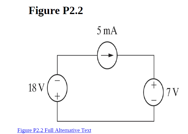
1. Is the interconnection of ideal sources in the circuit
valid? Explain.
2. Identify which sources are developing power and which sources are
absorbing power.
3. Verify that the total power developed in the circuit equals the total
power absorbed.
4. Repeat (a)–(c), reversing the polarity of the 18 V source.
Trending now
This is a popular solution!
Step by step
Solved in 3 steps with 6 images
- if i want building power supply out 9v. full wave rectifier ,Consists of source 240 voltage 50Hz , resistor and 2 capacitor and 4 dimes and transformer .what is the Equations and circuit diagram for it,and what is Values of components(i) With neat sketch explain the cross sectional view and I-V characteristics of the device which is having uncontrolled turn ON and turn OFF withstanding capability. (ii) Write FOUR application of the above mentioned power semiconductor device.Answer in Sentence/Paragraph form. Maximum of 5 sentences each. Lesson: Electronics: FULL-WAVE Rectifier with and without Filter1. What is the necessity of the transformer in the recitifer circuit?2. What are the applications of the rectifier? 3. What is meant by ripple and define ripple factor. 4. Explain how capacitors helps to improve the ripple factor. 5. Can a rectifier made in India (V=230 V , f=50Hz) be used in USA (V=110V, f=60Hz)?
- if i want building power supply out 9v. full wave rectifier ,Consists of resistor and 2 capacitor and 4 dimes and transformer .what is the Equations and circuit diagram for itA FW battery rectifier charges a 12V battery. Identify the transformer providing 0.2Ω series resistance, 10A current for 120VAA welding (Number of turns and kVA rating). Find the efficiency of the circuit for 1.4 V diode transmission voltage.Determine the potential Uab and the current IE1 in the figure
- A full wave bridge rectifier is supplied from 230V, 50Hz and uses a transformer of turns ration 15:1. It uses load resistance of 50 ohms. Calculate load voltage and ripple voltage. Assume ideal diode and transformer. Assume ripple factor equals to 0.482. a.Load Voltage= 13.8 V; Ripple Voltage=6.652 V b.Load Voltage= 15.6 V; Ripple Voltage=7.611 V c.Load Voltage= 21.3 V; Ripple Voltage=8.410 V d.Load Voltage= 25.1 V; Ripple Voltage=10.442 VDEVELOP AND JUSTIFY YOUR RESPONSE. Determine the total current when BT1 = 15.9 V, BT2 = 7.5 V, the Resistance R1 = 1.1 kΩ and the Resistance R2 = 4.4 kΩ, Consider voltage drop of the diodes of Si = 0.7V A. -2.55 mA. B. 1,40 mA. C. 4.25 mA. D. -1.53 mA.Consider the diodes D1, D2, and D3 type as Silicon, Germanium, and GaAs respectively. Calculate for the current in each diode, and the voltage across R1
- Single phase half wave controlled rectifier supplied from 150 V if the load is 10 ohm if the delay angle a =30 Find : 1- maximum load current 2-average load voltage 3- average load current 4-RMS load current 5-power supply to the load 6-conduction angle 7-power factorFind the current in D3 in AMPS V1=19 Volts, R1=7 Ω R2=13 Ω, R3=14 Ω VZD1=4 Volts, VZD2=10 Volts Note: Consider in your calculation the voltage of diodes if needed.Q2: For the single phase full wave semi controlled rectifier shown: 1-Draw the v-i waveforms for the circuit vm 2-Prove that: lav =~ (1+cos @) 3-Maximum voltage across the load if the AC supply voltage is 208V .