Figure Q3(b) shows a phase shift oscillator circuit. Given the feedback gain: i Determine an equation for frequency of oscillation ii Calculate the value of capacitors, C, if the output voltage is equal to 5 sin 3?? ?? and resistor, R is equal to 100 ??Ω. iii Calculate the open-loop gain, A, in order to generate an oscillating signal. iv Determine the value for ??1and ??2 in order to generate an oscillating signal. You may refer to the Appendix in page 5 and 6 for the commercial value of resistor.
Figure Q3(b) shows a phase shift oscillator circuit. Given the feedback gain: i Determine an equation for frequency of oscillation ii Calculate the value of capacitors, C, if the output voltage is equal to 5 sin 3?? ?? and resistor, R is equal to 100 ??Ω. iii Calculate the open-loop gain, A, in order to generate an oscillating signal. iv Determine the value for ??1and ??2 in order to generate an oscillating signal. You may refer to the Appendix in page 5 and 6 for the commercial value of resistor.

Delmar's Standard Textbook Of Electricity
7th Edition
ISBN:9781337900348
Author:Stephen L. Herman
Publisher:Stephen L. Herman
Chapter16: Inductance In Ac Circuits
Section: Chapter Questions
Problem 1PP: Inductive Circuits Fill in all the missing values. Refer to the following formulas:...

Related questions
Question
Figure Q3(b) shows a phase shift oscillator circuit. Given the feedback gain:
i Determine an equation for frequency of oscillation
ii Calculate the value of capacitors, C, if the output voltage is equal to
5 sin 3?? ?? and resistor, R is equal to 100 ??Ω.
iii Calculate the open-loop gain, A, in order to generate an oscillating signal.
iv Determine the value for ??1and ??2 in order to generate an oscillating
signal. You may refer to the Appendix in page 5 and 6 for the commercial
value of resistor.
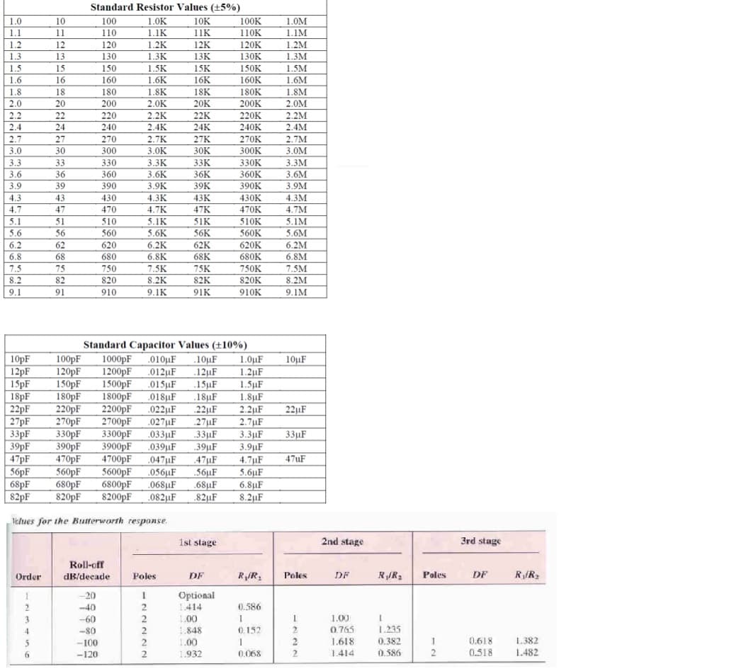
Transcribed Image Text:Standard Resistor Values (+5%)
1.0
10
100
1.0K
10K
100K
1.0M
1.1
11
110
1.1K
11K
110K
1.1M
1.2
12
120
1.2K
12K
120K
1.2M
1.3м
1.5M
1.3
13
130
1.3K
13К
130K
1.5
15
150
1.5K
15K
150K
1.6
16
160
1.6K
16K
160K
1.6M
180K
200K
1.8
18
20
180
1.8K
18K
1.8M
2.0
200
2.0K
20K
2.0M
2.2K
2.4K
2.2
22
220
22K
220K
2.2M
2.4
24
240
24K
240K
2.4M
2.7
27
270
2.7K
27K
270K
2.7M
3.0
30
300
3.ОК
30K
300K
3.0M
33K
330K
360K
390K
3.3
33
330
3.ЗК
3.3М
360
390
3.6
36
3.6K
3.6M
3.9K
4.3K
4.7K
36K
39K
43K
3.9
39
3.9M
4.3
43
430
430K
4.3M
4.7
47
470
47K
470K
4.7M
5.1
5.6
51
510
5.1K
51K
56K
510K
5.1M
56
560
5.6K
560K
5.6M
6.2
62
620
6.2K
62K
620K
6.2M
6.8
68
680
6.8K
68K
680K
6.8M
7.5
75
750
7.5K
75K
750K
7.5M
8.2
820K
910K
82
820
8.2K
82K
8.2M
9.1
91
910
9.1K
91K
9.1M
10pF
12PF
15pF
18PF
22PF
27PF
33pF
39PF
47PF
56PF
68pF
82pF
100pF
120pF
150pF
180pF
220pF
270pF
330pF
390pF
470PF
560PF
680pF
820pF
Standard Capacitor Values (±10%)
1000pF
1200pF
1500pF
1800PF
2200pF
2700pF
3300pF
3900pF
4700pF
5600pF
6800PF
8200pF
.010µF
.012µF
.015µF
.018uF
.022µF
.027HF
.033µF
.039µF
.047µF
056µF
.10µF
.12µF
.15µF
.18µF
.22µF
.27µF
.33µF
39µF
1.0µF
1.2µF
1.5µF
1.8µF
2.2µF
2.7µF
3.3µF
3.9µF
4.7µF
5.6µF
6.8µF
8.2µF
10µF
22µF
33µF
.47µF
47UF
56µF
.68µF
.82µF
.068µF
.082uF
Velues for the Butterworth response.
1st stage
2nd stage
3rd stage
Roll-off
Order
dB/decade
Poles
DF
RJR,
Poles
DF
RJR2
Poles
DF
R/R2
-20
Optional
1.414
2
-40
0.586
3.
-60
1.00
1.00
-80
2
1.848
0.152
2.
0.765
1.235
0.618
0.518
1.382
1.482
-100
1.00
1.618
0.382
-120
1.932
0.068
1.414
0.586
2
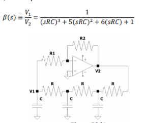
Transcribed Image Text:B(s)
V2 (SRC)³ + 5(sRC)² + 6(sRC) + 1
R2
R1
v2
www.ww
V1
Expert Solution
This question has been solved!
Explore an expertly crafted, step-by-step solution for a thorough understanding of key concepts.

Step by step
Solved in 2 steps

Knowledge Booster


Learn more about
Need a deep-dive on the concept behind this application? Look no further. Learn more about this topic, electrical-engineering and related others by exploring similar questions and additional content below.Recommended textbooks for you
Delmar's Standard Textbook Of Electricity
Electrical Engineering
ISBN:
9781337900348
Author:
Stephen L. Herman
Publisher:
Cengage Learning

EBK ELECTRICAL WIRING RESIDENTIAL
Electrical Engineering
ISBN:
9781337516549
Author:
Simmons
Publisher:
CENGAGE LEARNING - CONSIGNMENT
Delmar's Standard Textbook Of Electricity
Electrical Engineering
ISBN:
9781337900348
Author:
Stephen L. Herman
Publisher:
Cengage Learning
EBK ELECTRICAL WIRING RESIDENTIAL
Electrical Engineering
ISBN:
9781337516549
Author:
Simmons
Publisher:
CENGAGE LEARNING - CONSIGNMENT