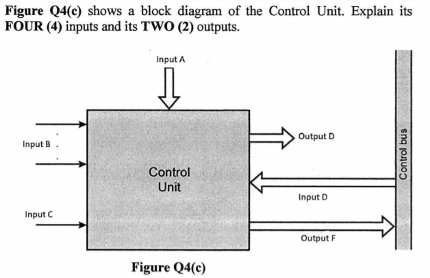
Figure Q4(c) shows a block diagram of the Control Unit. Explain its FOUR (4) inputs and its TWO (2) outputs.


Q: HW4 For the sequential logic circuit below; 1- How many inputs are there? What are they? 2- How many…
A: 1. Total number of inputs = 10 Constitution of Inputs: 2 for XOR gate with one input as W. 2 for…
Q: Draw a plc ladder diagram for blinking lights with start and stop button. Please help me with this.…
A: The answer of this question is as follows:
Q: label each of the devices
A: The devices used in the logical circuit diagram: Resistor The resistor is represented by the…
Q: الم ملكة العربية السعودية وزارة التعليم العالي KINGDOM OF SAUDI ARABIA Ministry of Higher Education…
A: A magnitude digital Comparator is a combinational circuit that compares two digital or binary…
Q: (b) Describe the state diagram below in detail. Hint: This state machine describes the operation of…
A: State diagram:- A state diagram is applied to show the state of the system. It’s a type of…
Q: Find the values of the flags (carry ,sign ,zero, overflow) of the processor status register for the…
A: Answer: given two 8 bit no's in Hex are: A7+EF in order to add those two numbers first convert both…
Q: A combinational logic circuit has three inputs with sequence A, B, and C and two outputs with…
A: I think there should be 8 possible state box for drawing ASM chart.
Q: Design logic circuit for ATM machine or Car Park Part A – Combinational logic circuit – One…
A: Digital Comparator The Digital Comparator is another very useful combinational logic circuit used…
Q: The input of an IC requires a constant 5 V, but the supply voltage is 9 V. Use the voltage divider…
A: Please find the answer to the above question below:
Q: Q1: For the following ASM chart a) Drive the equivalent State Diagram. b) Make the best possible…
A:
Q: C1. The figure below shows the state diagram of a synchronous circuit to detect the sequence 110.…
A:
Q: Draw a space-division THREE (3) stages switches. There are 9 inputs and 16 outputs. Stage 1 has…
A:
Q: Design and Draw the Full circuit diagram for the third and fourth Instructin Cycles ( Read the…
A: The solution is given below:
Q: Design and implement sequential digital circuit, with following specifications: It has one input X,…
A: Here, I have to provide a solution to the above question.
Q: How will your lift controller react if 40 is loaded as a floor number? Discuss the changes you might…
A: Solution:-- 1)As given in the question is to provide the VHDL code for the lift controller…
Q: Q2. Give three examples of closed loop and open loop control systems illustrating the advantage and…
A: example of an close loop system: Thermostat Heater The thermostat heater is an example of closed…
Q: 7- Simulation tests all the logic a. Gate speed b. Functions c. Tools 8- EDA test bench creation…
A: i have provided this answer with full description in step-2.
Q: Find a ready-made combined logic circuit description or write it yourself directly. The module…
A: Find a ready-made combined logic circuit description or write it yourself directly. The module…
Q: A combinational logic circuit has three inputs with sequence A, B, and C and two outputs with…
A: let us see the answer:- the correct answer is 3
Q: Draw the logic diagram of the digital circuit specified by the following Verilog description: module…
A:
Q: Describe the general setup for an arduino board when used to design a digital system
A: Here have to determine about general setup for an arduino board when used to design a digital…
Q: Draw the circuit diagram to output F given in the expression above by referring to schematics for…
A:
Q: (b) Draw the functional block diagram of the controller.
A: Draw the functional block diagram of the controller.
Q: onstruct the state diagram, primitive flow table and reduced flow table for a fundamental mode…
A: ANSWER: Primitive Flow Table: A primitive flow table is a flow table with just one stable absolute…
Q: Design a PLC program and prepare a typical I/O connection diagram and ladder logic program for the…
A: In the question, the following data is given. A motor named M and three controlling START/STOP…
Q: 10. Consider the following state diagram of control unit, that has four states and two inputs x and…
A:
Q: Problem 1: Your task for this problem is to build your own ALU in the simulator (you cannot use the…
A: Solution :: Before going to main question Let's see first what is truth table and k-map ? Answer ::…
Q: Write an assembly program to control in speed and direction of DC-Motor based on the states of the…
A: Assembly program
Q: Write an assembly program to control in speed and direction of DC-Motor based on the states of the…
A: Answer: Code 1- #include <REGX51.H> void delay(void); sbit m1_pin1 = P2^0; sbit m1_pin2 =…
Q: The designer needs for...... stat boxes for drawing the ASM chart for the controller of the…
A: The designer needs for 8 state boxes for drawing the ASM chart for the controller of the…
Q: draw single cycle Datapath and control signals 1. for Add rd,rs,rt 2. during Load 3. during Store
A: draw single cycle Datapath and control signals 1. for Add rd,rs,rt 2. during Load 3. during…
Q: Draw a state diagram for an FSM without inputs. Three outputs include a, b, and c. abc must exhibit…
A: Draw a state diagram for an FSM without inputs. Three outputs include a, b, and c. abc must exhibit…
Q: Write an assembly program to control in speed and direction of DC-Motor based on the states of the…
A: //Arduino DC motor speed and direction control #define button 8 #define pot 0 #define pwm1…
Q: What are the design criteria for combinational circuits and how do they differ?
A: To discuss about the design criteria for combinational circuits and how do they differ from…
Q: The Verilog code in Listing Q2a describes a digital system using hierarchical design methodology.…
A: Introduction: As per the given problem statement, find the way using the street and develop a python…
Q: Draw a state diagram for an FSM without inputs. Three outputs include x, y, and z. xyz must exhibit…
A:
Q: Consider the ASM CHART. Design only the control logic of the system. Answer the following: a.…
A: a) In ASM chart there are three components. They are i) state box, ii) Decision box, iii) condition…
Q: Design and implement sequential digital circuit, with following specifications: It has one input X,…
A: the solution for the above-given question is given below:
Q: 7- Simulation tests all the logic a. Gate speed b. Functions c. Tools 8- EDA test bench creation…
A: Question 7: Logic simulation is a way of testing a system on a computer before it is turned into…
Q: Draw the circuit diagram to output F given in the expression above by referring to schematics for…
A:
Q: Qla) Draw the block diagram of Programmable Peripheral Interface (32C55) and label its all ports and…
A: According to the information given:- We have draw block diagram of Programmable Peripheral Interface…
Q: The designer needs for ...... conditional output boxes for drawing the ASM-chart for the controller…
A: The solution to the given question is: The designer needs for six conditional output boxes for…
Q: What's the behavioral, register-transfer, and gate-level of a FLIP-FLOP circuit and include its…
A: What's the behavioral, register-transfer, and gate-level of a FLIP-FLOP circuit and include its…
Q: draw a QPSK demodulator circuit using different circuit component
A: QPSK demodulator circuit:
Q: If the controller of a system is a computer, the controlled signal is sent to the actuator: a.…
A: It is defined as a part of a device or machine that helps it to achieve physical movements by…
Q: Q8/ Draw the state diagram and state table of a circuit that serially check non BCD code. The output…
A:
Q: each of the light configurations shown in Figure 1. 000 100 010 110 001 Figure 1. A state diagram…
A: The answer given as below:
Q: A) What does VCO stand four? Show by drawing the relationship between its input and output signals.…
A: VCO stands for Voltage Controlled Oscillator. A Voltage Controlled Oscillator is an oscillating…
Q: Write the working principle, design, circuit diagram and precaution of Shift Registor
A: Working principle: Shift registers are used for data storage.it is commonly used in pc and…


Trending now
This is a popular solution!

Step by step
Solved in 2 steps with 1 images


- Explain the basic function of a Bus Interface Unit (BIU) and an Execution Unit (EU) in a brief way (EU) (EU).MIPS Datapath: Implement a single cycle datapath that supports the following instructions: beq, bne, jump, andi, and, add,lw, sw Show only the components needed. Clearly label all lines and components (including the number of bits per line if appropriate). Draw the table for ALUop Draw the table for the Main Controller. There should be a row for every instruction and a column for every control signal.Considering the 3 bus SRC write the concrete RTN and control sequence for and ra,rb,rc.Explain why is it different from that of 1 bus SRC
- Draw the 8259 microcontroller Internal block diagram. And explain how it works.Draw the control unit and datapath for the following algorithm that returns an integer value. The function takes two points (x1, y1) and (x2, y2) and computes the equation for a line. It then evaluates and returns ynew for the parameter xp using that line. Use a 16-bit data bus. Show your work; label and clearly mark your diagram. Do not implement this in VHDL. int PredY(int x1, int y1, int x2, int y2, int xp) { int m, b, ynew; if (x1 – x2) <> 0 { m = (y1 - y2) / (x1 - x2); b = y1 - m * x1; ynew = m * xp + b; return(ynew); } else { return(65535); // that's a 16-bit FFFF } }Why Data Bus is bidirectional