Find the cross correlation of functions sin o t and cos ot

Power System Analysis and Design (MindTap Course List)
6th Edition
ISBN:9781305632134
Author:J. Duncan Glover, Thomas Overbye, Mulukutla S. Sarma
Publisher:J. Duncan Glover, Thomas Overbye, Mulukutla S. Sarma
Chapter3: Power Transformers
Section: Chapter Questions
Problem 3.44P: A 130-MVA,13.2-kV three-phase generator, which has a positive-sequence reactance of 1.5 per unit on...

Related questions
Question
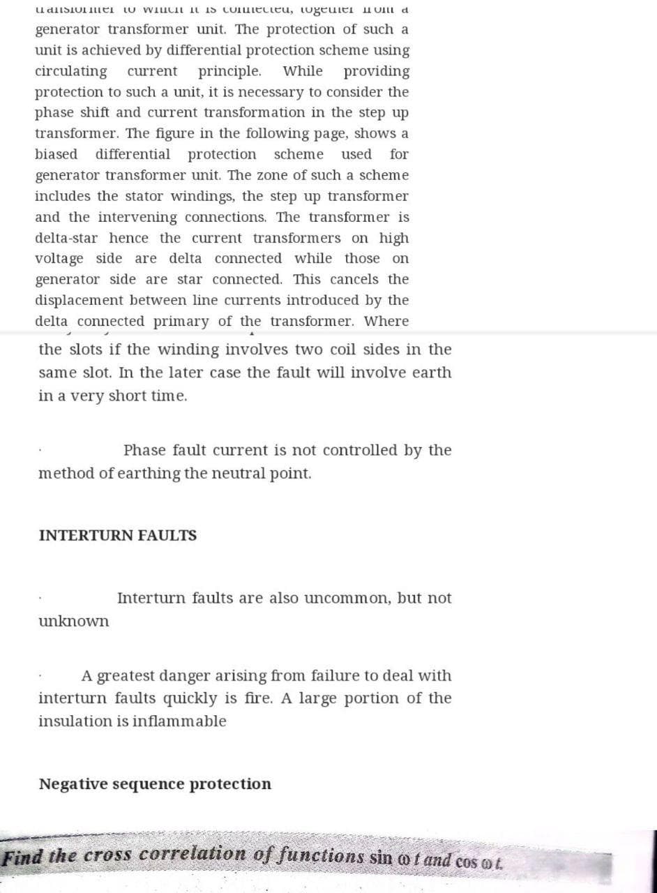
Transcribed Image Text:udisiol ei tu WiuCI iN is CoIuiecteu, tugeulei uUI a
generator transformer unit. The protection of such a
unit is achieved by differential protection scheme using
circulating
protection to such a unit, it is necessary to consider the
phase shift and current transformation in the step up
transformer. The figure in the following page, shows a
current
principle.
While
providing
biased
differential protection scheme
used
for
generator transformer unit. The zone of such a scheme
includes the stator windings, the step up transformer
and the intervening connections. The transformer is
delta-star hence the current transformers on high
voltage side are delta connected while those on
generator side are star connected. This cancels the
displacement between line currents introduced by the
delta connected primary of the transformer. Where
the slots if the winding involves two coil sides in the
same slot. In the later case the fault will involve earth
in a very short time.
Phase fault current is not controlled by the
method of earthing the neutral point.
INTERTURN FAULTS
Interturn faults are also uncommon, but not
unknown
A greatest danger arising from failure to deal with
interturn faults quickly is fire. A large portion of the
insulation is inflammable
Negative sequence protection
Find the cross correlation of functions sin o f and cos ot
Expert Solution
This question has been solved!
Explore an expertly crafted, step-by-step solution for a thorough understanding of key concepts.

Step by step
Solved in 2 steps with 2 images

Knowledge Booster


Learn more about
Need a deep-dive on the concept behind this application? Look no further. Learn more about this topic, electrical-engineering and related others by exploring similar questions and additional content below.Recommended textbooks for you
Power System Analysis and Design (MindTap Course …
Electrical Engineering
ISBN:
9781305632134
Author:
J. Duncan Glover, Thomas Overbye, Mulukutla S. Sarma
Publisher:
Cengage Learning
Power System Analysis and Design (MindTap Course …
Electrical Engineering
ISBN:
9781305632134
Author:
J. Duncan Glover, Thomas Overbye, Mulukutla S. Sarma
Publisher:
Cengage Learning