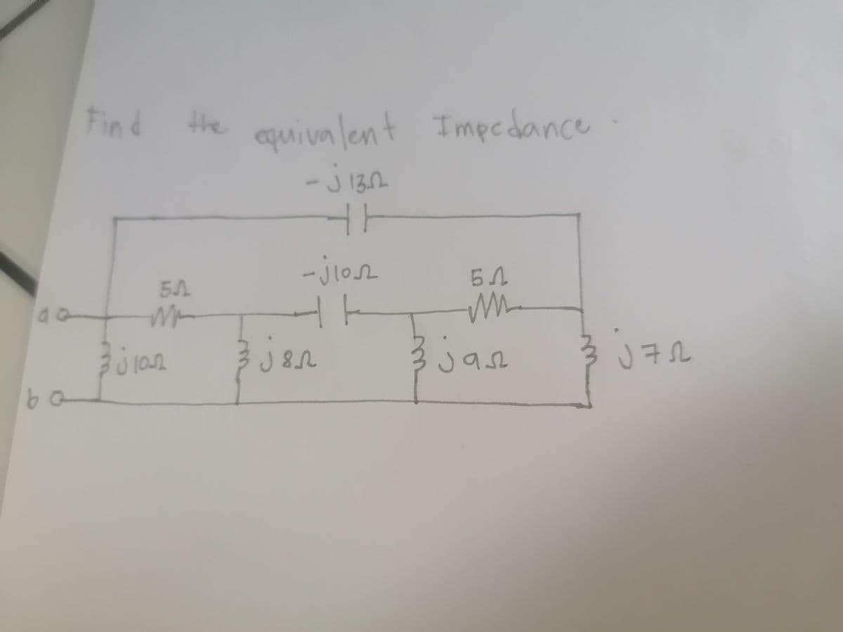
Find the equivalent 5.A 3 j1022 130 ن - -jon t jsn Impedance 5A i jas J72


Q: A three-phase substation bus supplies a wye and a delta connected constant impedance loads. The…
A: Solution
Q: A. Make a diagram of a series circuit comprising of a switch, a 100V battery, and 3 loads. B.…
A: In series connection the elements should be connected back to back and in parallel connection the…
Q: The binary string 11b10010111110 is a floating-point number expressed using the 14-bit simple model…
A: Given,Using the 14-bit simple model,The binary string in floating-point number is,X=11010010111110
Q: does line current need Vrms or the given peak voltage to be
A: In this question we will write about line current....
Q: Write the differential equations of motion, convert to Laplace domain with zero initial conditions.…
A: b) Calculation of ODE of the system The mechanical system is given as Given data k1=k2=2m1=m2=1c=1
Q: Class C commutation technique is forced commutation technique O complementary commutation technique…
A: We are authirized to answer only 1 question at a time since you have not mentioned which question…
Q: Find Vo by using nodal analy sis 12K 6 Kr ÓKe 12U( VO -
A:
Q: Do you think that the design procedure is easy using multiplexer?
A: Multiplexer: The multiplexer is a common sensetool that switches one in allseveraenterstrains to a…
Q: 1) What are the methods of measuring high voltage AC 2) explain common method used for measuring…
A: 1) methods of High voltage measurement are given below: Potential divider(resistance or capacitive…
Q: 25-x dy dx C)
A: The above Integration can be solved by using the properties of the Integration by parts. Solution…
Q: Show in block diagram:( choose one) (A) Simplified view of PLC. (B) Expanded view of PLC.
A:
Q: Compose the nodal equations. Multiply with the least common factor to remove fractions.
A: calculation of node eq. for the circuit: According to nodal analysis the sum of total current in a…
Q: An analog-to-digital (A/D) converter has a 15-bit binary input. The input analog voltage range is 0…
A:
Q: A unity feedback system has the open loop transfer function shown below. Use the Nyquist Path which…
A: Given data, HG(s)=k(1+s)s21+s102
Q: Design and implement a BCD–to–seven-segment decoder using basic gates
A: The required digital circuit can be designed by using the truth table and the Boolean expression can…
Q: Solve the follwoing questions with complete solution. Question 6 Show that the same work is done in…
A: Solution- Work done for moving a charge to point ( 0,0,0) to ( 1,2,3), We know, F→=-qE→ dl→…
Q: What incremental energy (in picojoules) is needed to move a 1 – µC charge an incremental distance of…
A: Energy: Energy is the ability to do a activity. Energy is stored in several forms, including…
Q: Assuming ideal op-amps (A, = co, Rin = c0, and Rout = 0), design R, and R for a trans-conductance…
A: The opamp circuit is given as The circuit can be redrawn as
Q: If an AM modulator has a carrier frequency of 1.1MHz and the input signal has a frequency of 2kHz,…
A: Given data is shown below. For an AM modulator carrier frequency fc=1.1MHz Message signal frequency…
Q: 3 If D = 4x a - 3za, + 2ya C/m, find the following: V•D
A:
Q: 1. A given conductor has a resistance of 1.5 . Find the resistance of another conductor having a…
A:
Q: FIND: 11 12 Id2 102 Si 12 Si 5.6K 20V source 3.3K
A: Given data from circuit , Assume ideal silicon diode The supply voltage is =20 V
Q: draw root locus diagrams for the following two transfer functions. With working that includes real…
A: “Since you have asked multiple questions, we will solve the first question for you. If youwant any…
Q: What is the low frequency input resistance, Ri, in Q for the amplifier shown at 27° C with Rd =…
A: Given data, The drain resistance (Rd) = 23.1kΩ The source resistance (RS) = 0.2kΩ The gain…
Q: Forthe followingtransferfunctions of control syste ms, determine the peak fre quency response gain,…
A:
Q: a) Determine the values of R and C needed to replace the capacitors and resistors of the left…
A:
Q: Determine the Nyguist sampling rate and the Nyquist sampling interval for the signals: (b) sinc?…
A:
Q: Vsz Rz Iz RI -+ 3 4 R 3
A:
Q: A filter is provided with a cascaded differential amplifier. The midband gain and noise coefficient…
A: The diagram of a cascaded differential amplifier with filter is shown below, The midband gain is −3…
Q: Draw the diagram of a 2-bit asynchronous ripple counter using T flip-flops and a 5-bit ring counter…
A: We need to draw the diagram of a 2-bit synchronous ripple counter using T flip-flops and a 5-bit…
Q: Q:Find the result of the following program AX=0002.Find the result AX= MOV BX, AX ASHL BX ADD AX, BX…
A: Given AX=0002 And a program. We need to find the output of the program. Please find the below…
Q: what are the factors (e.g.., drain current) that affect the VGS input for a voltage divider CS…
A: A FET is a electronic component used in power electronics applications. There are different…
Q: 30s 251 65m 1502 1435 2014 22o 50 For the ciccull shown find ZR,ZL,ZIT, VRT V Vc. Cin complex)
A:
Q: AT=5 ps transform-limited pulse propagates in a dispersive medium for which ß2 = 10 ps²/km. Over…
A: Writing the expression for pulse spread,Tp=T2+∆τ2 .......1Here,Tp=pulse spread∆τ=change in…
Q: Note: Answer (All) questions only Q1: Find The Fourier series for the function defined by 0 < x <4 1…
A:
Q: * uhat is the gate for Cmenit Bo Vo *. when infut" 1" = 6v %3D infut o = 0v %3D REDMI NOTE 8 PRO
A: Here we discuss the realization of 3 input logic gate using diode circuits.
Q: See the attached photo and answer it
A: Since you have asked multiple questions in a single request, we will be answering only the 1st…
Q: e) The block diagram in the figure represents the series connection of a ZOH, a continuous time…
A: Given The block diagram in the figure represents the series connection of a ZOH, a continuous time…
Q: Determine Vo and I Si Vo 4.7Ke 12V
A:
Q: We want to design a causal discrete-time LTI system with the property where the input is z(n) =…
A: We want to design a causal discrete-time LTI system with the property where the input is:…
Q: Convert the following decimal Real number to fixed point binary: 19.62510 Assume 8 bits for the…
A:
Q: The noise coefficient of a microwave receiver front section is desired to be measured by the…
A: Solution
Q: a 4-bit Gray Code to Excess-3 code converter
A: Code convertors- These code converters are used for conversion of one type of binary code to…
Q: Convert the State Space to Transfer function, (b) Draw a Block diagram of the system = , )*+Gr) х y…
A: State Space Analysis: State space analysis provides the overall idea about the behavior of the…
Q: 3. List the losses in SPIM. 4. What are types of SPIM. 5. What are the disadvantages of SPIM. 6.…
A:
Q: A metallic wire is stretched from original length of 1 m to 5 m. If the original cross-sectional…
A:
Q: 4.10) A buck regulator has an input voltage of 12 V and the required output voltage is 5 V. What is…
A:
Q: A magnetic circuit made of mild steel is arranged as shown in Fig.3. The cent.ral limb is wound with…
A:
Q: 1. By using dv and volume integral in spherical coordinate, find the volume of a sphere with a…
A: We are authorized to answer one question at a time, since you have not mentioned which question you…
Q: At resonance Select one: a. magnitude of capacitive reactance > magnitude of inductive reactance.…
A: Ralation between inductive and capacitive reactance at resonance:

Step by step
Solved in 3 steps with 3 images


- Let a 100V sinusoidal source be connected to a series combination of a 3 resistor, an 8 inductor, and a 4 capacitor. (a) Draw the circuit diagram. (b) Compute the series impedance. (C) Determine the current I delivered by the source. Is the current lagging or leading the source voltage? What is the power factor of this circuit?If a load is symmetric with 50 ohm of series impedance and 13 ohms of mutual impedance, what are the sequence impedances? a. z11 = z22 = 63 ohm, z33 = 89 ohm, else 0 b. z11 = z22 = 33 ohm, Z00 = 76 ohm, else 0 c. z11 = z22 = 50 ohm, Z00 =89 ohm, else 0Impedance of AC circuit and Admittance of AC circuitSHOW THE CIRCUIT USING ANY SOFTWARE OR YOU CAN DRAW IT MANUAALYY thNAKSS
- Two impedances are fed by a source with V = 100Vrms 160 °, as shown below. The total current is I = 2Arms 190 ° ,and the first load consumes P1 = 23.2W and Q1 = 50 var. Calculate a) currents I1 and I2b) the power factor of each impedancec) the total power factor of the circuitWhich termination would result to a phase change of 180 degrees at the load if Zo = 100 ohm? a. 50 ohm b. short circuit c. 75 ohm d. all of these What is the purpose of impedance matching? a. maximum return loss b. maximum SWR c. maximum load power d. maximum reflection A short piece of transmission line that may be open or shorted and used for impedance matching purposes. a. converter b. decoder c. stub d. transformerSketch the phasor diagram of the above circuit in terms of impedance, voltage, and the power triangle.
- Give example problems for impedances. Equation: Z = R ± jX or Z2 = R2 + X2A balanced positive-sequence three-phase source hasvan(t)=100 cos(377t+90°) V a. Find the frequency of this source in Hz. b. Give expressions for vbn(t) and vcn(t) c. Repeat part (b) for a negative-sequence source.ZL impedance for maximum average power transfer in the circuit shown in Figure 2and find the value of the maximum average power transferred to the ZL? (Can you write the steps in detail in sentences?)
- Two impedances Z1 and Z2 are connected in parallel. Find the equivalent impedance, if Z1 =7 +j3 ohm and Z2 =17 -j13 ohm .Using the node-voltage method, determine the magnitude of the phasor voltage V1; that is, find |V1| in Volts (peak). The values of the phasor voltage sources in the above diagram are VA = 3 and VB = 3 Volts. The resistor values are R1 = 4 Ω and R2 = 8 Ω, and X1 = 12 for the capacitor giving an impedance of -j12 Ω. Express your answer using 3 significant figures.ee circuits a. Three impedances each (10 + j5) Ω are connected in delta on a balance 3-phase source. If the equation of the phase voltage is ?an = 120 sin ??, find the equation of the current through the impedance connected across phase a and b.